Turning vane for air duct

a technology of air ducts and turning vanes, which is applied in the direction of lighting and heating apparatus, space heating and ventilation details, heating types, etc., can solve the problems of substantial pressure loss and/or undesirable vibration and noise, and achieve the effects of strong and inexpensive, easy assembly and installation, and strong and reliable after installation

Active Publication Date: 2010-06-24
CAPITAL HARDWARE SUPPLY LLC
View PDF20 Cites 37 Cited by
  • Summary
  • Abstract
  • Description
  • Claims
  • Application Information

AI Technical Summary

Benefits of technology

[0008]A first object is to provide an improved air-turning vane and rail assembly which is both strong and

Problems solved by technology

If the air flowing through the ductwork becomes turbulent because of the change of dire

Method used


Image

  • Turning vane for air duct
  • Turning vane for air duct
  • Turning vane for air duct

Examples


Embodiment Construction

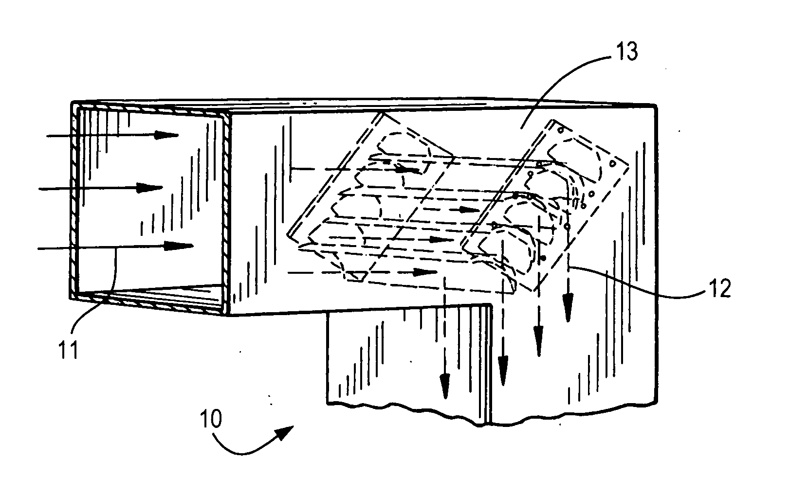
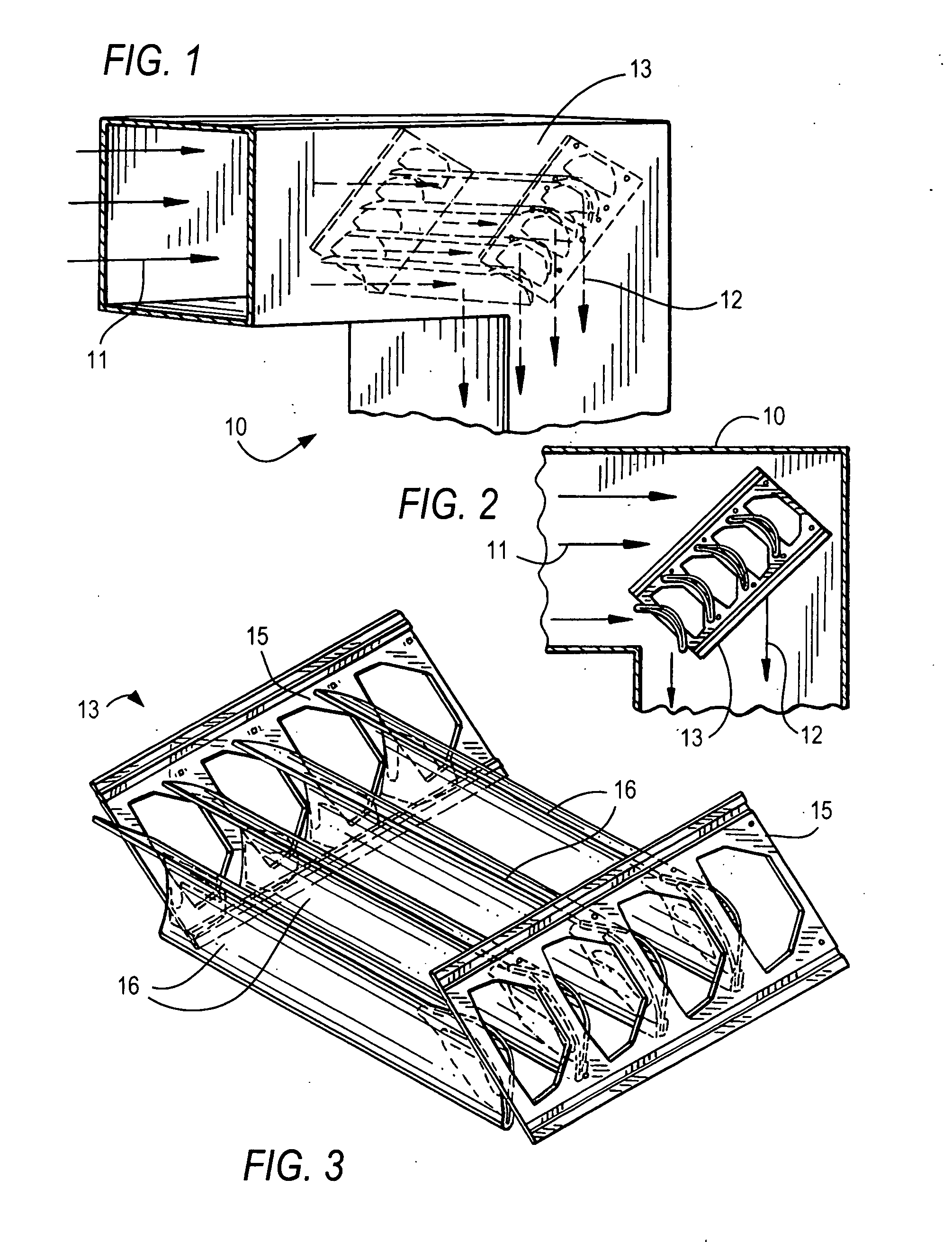
[0056]FIGS. 1 and 2 illustrate a typical air duct 10 which includes a right angle turn, thus requiring air flow 11 to make a 90° turn to continue as air flow 12. Turning is efficiently achieved through turning vane assembly 13, as further described below.

[0057]FIG. 3 shows a fragmentary view of the turning vane and rail assembly 13 comprising spaced apart rails 15 to which are attached turning vanes 16.

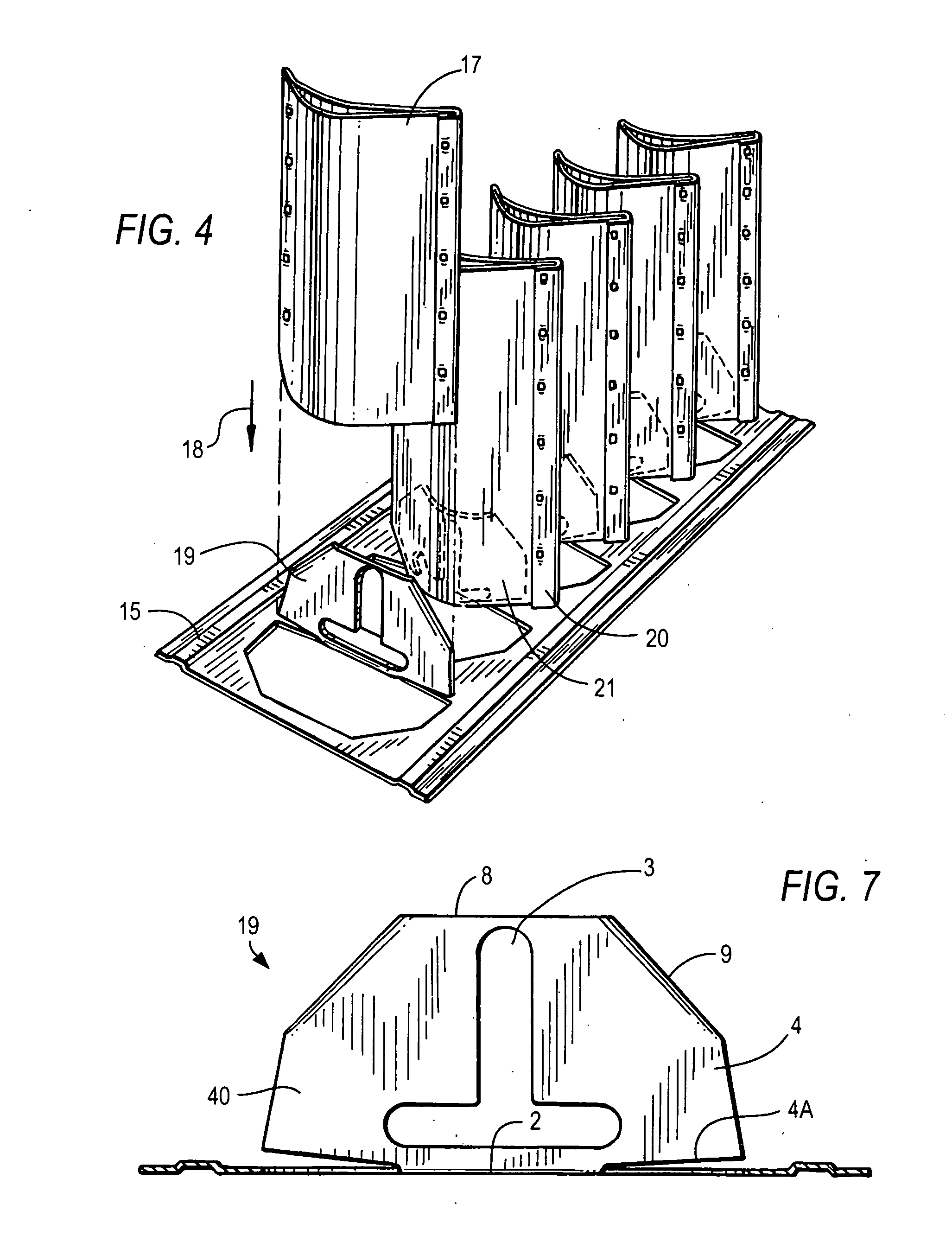
[0058]Attachment of each turning vane 16 to one rail 15 is illustrated in FIG. 4, where vane 17 is moved in the direction of arrow 18 toward upward-extending tab 19 which is punched and bent 90° out of the plane of rail 15. Also in FIG. 4 is shown an adjacent vane 20 descending downward on its corresponding tab 21 and secured thereto.

[0059]FIGS. 5, 6 and 7 are top, side elevation and end elevation views respectively of one rail 15 with tabs 22, 23, 24 and 25. As seen in FIGS. 5 and 6, tab 22 is in its initial punched but not-bent state, tabs 23 and 24 are bent into their erect positio...


PUM


Abstract

An air turning vane and rail assembly for promoting laminar air flow in an angled duct work section, including a pair of rails in parallel spaced apart relation, each of the rails having an elongated body part and a plurality of tabs spaced apart from each other punched from and bent to extend generally perpendicular to the body part in a height distance H, and a plurality of air turning vanes in parallel and spaced apart relation to each other and situated between and perpendicular to the rails in a ladder-like assembly, each of the turning vanes including a single sheet of metal that is folded in a U-bend to form elongated generally rectangular upper and lower walls, each wall having opposite end edges, the vane defining a lengthwise axis extending between the opposite ends, the upper wall in end view defining an arc of first radius of curvature, and the lower wall in end view defining an arc of second radius of curvature greater than the first radius of curvature, with a crescent shaped space defined between the upper and lower walls, and a plurality of crimp spots spaced apart from each other in the lengthwise direction for stabilizing the upper and lower walls in the vane configuration, each crimp spot extending transversely through the marginal portions of the upper and lower walls, each two adjacent crimp spots being spaced apart from each other in the lengthwise direction a distance L which is less than the distance H, and in each of the crescent shaped spaces in ends of the vanes one of the tabs being inserted and bent to generally conform to and fit snugly.

Description

RELATED CASES[0001]This application claims priority under 35 U.S.C. §119,120 and or 365 on Provisional Application Ser. No. 61 / 203,722 filed Dec. 23, 2008.I. BACKGROUND[0002]A. Field of the Invention[0003]This invention is directed to air turning vane and rail assemblies utilized in ventilation and air conditioning ducts in commercial, industrial and residential buildings.[0004]B. Background and Prior Art[0005]Turning vane and rail assemblies are positioned within ducts to promote laminar flow of the air within the duct during the directional change of the air as it flows through the duct. Ventilation and air conditioning ductwork used in buildings is typically formed of straight rectangular cross section tubes which may change direction as much as 90 degrees through the use of transition sections or simply by forming the sheet metal ducts in such a manner as to make the turn. If the air flowing through the ductwork becomes turbulent because of the change of direction, there can be ...

Claims


Application Information

Patent Timeline
IPC IPC(8): F15D1/04
CPCF24F13/081F15D1/04
Inventor YOSKOWITZ, DAVID
Owner CAPITAL HARDWARE SUPPLY LLC
Why Eureka
Try Eureka