Select fill sensor system for refrigerator dispensers

a sensor system and refrigerator technology, applied in the field of refrigerators, can solve the problems of mechanical and membrane switch wear, springs, levers, lack of automatic cut-off feature, etc., and achieve the effect of avoiding overflow or spill events

Active Publication Date: 2010-06-24
WHIRLPOOL CORP
View PDF46 Cites 51 Cited by
  • Summary
  • Abstract
  • Description
  • Claims
  • Application Information

AI Technical Summary

Benefits of technology

This patent describes an optical sensing system used in a dispenser assembly to monitor how quickly a container is filling up with products. It uses a camera placed inside the dispenser well to detect if there's a container present and selects the type of product needed based on this detection. The system then controls the speed at which the product is dispensed to ensure optimal filling without causing any issues like overfilling or spills. Overall, it provides better efficiency and accuracy when dispensing various types of products from containers.

Problems solved by technology

This patent describes various issues with current refrigerator dispensers including their design (mechanical or electronic), functionality (single or double acting) and limitations when detecting containers (sensors). There is a technical problem of providing an improved refrigeration dispensing system that can handle different types of containers and prevent accidental spills.

Method used


Image

  • Select fill sensor system for refrigerator dispensers
  • Select fill sensor system for refrigerator dispensers
  • Select fill sensor system for refrigerator dispensers

Examples


Embodiment Construction

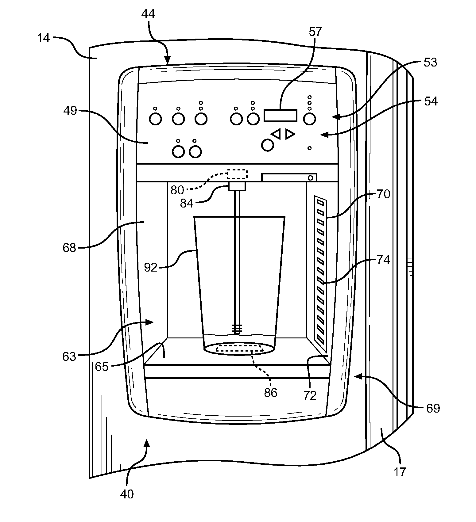
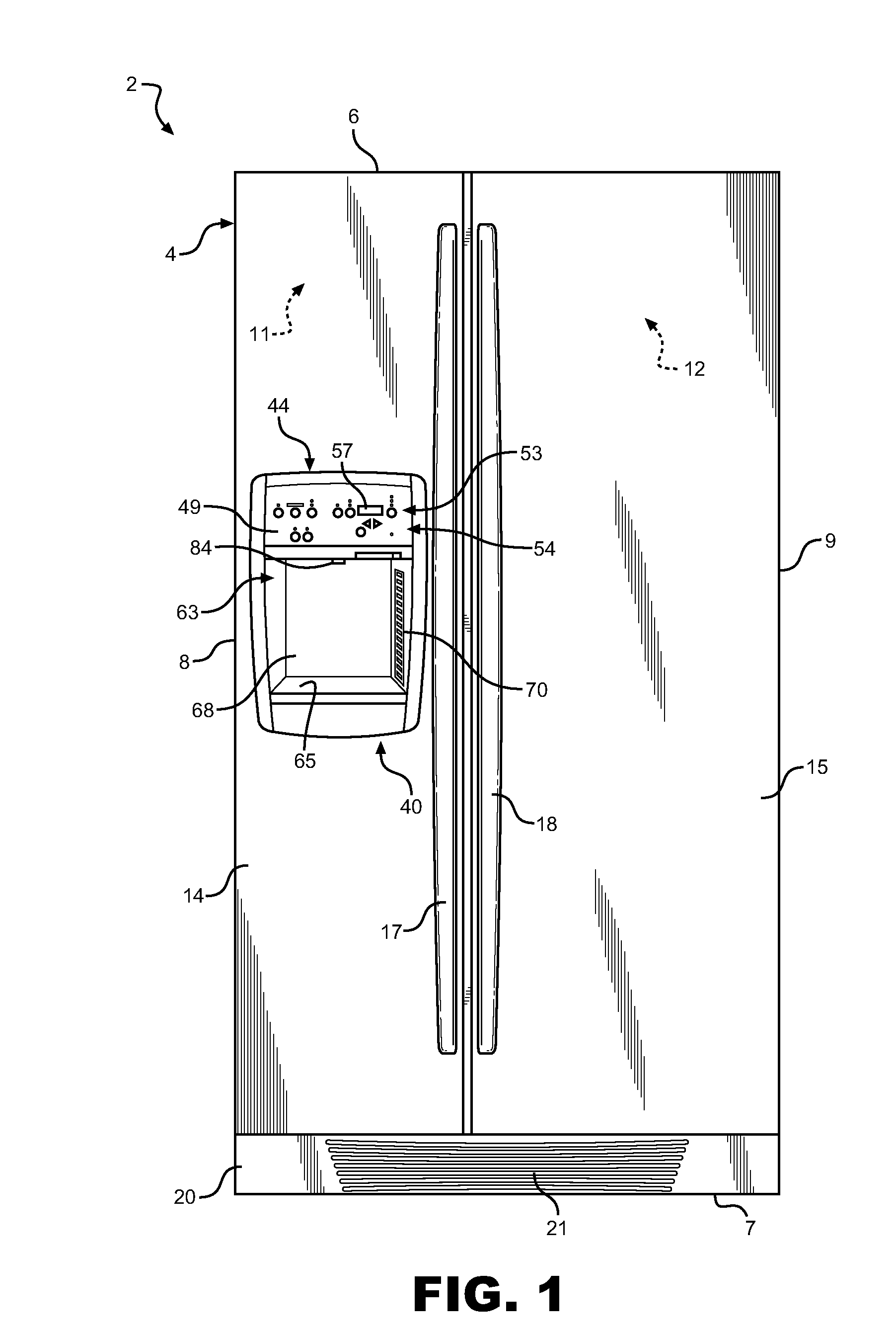
[0018]With initial reference to FIG. 1, a refrigerator constructed in accordance with the present invention is generally indicated at 2. Refrigerator 2 includes a cabinet 4 having a top wall 6, a bottom 7 and opposing side walls 8 and 9. In a manner known in the art, refrigerator 2 includes a freezer compartment 11 arranged along side a fresh food compartment 12. Freezer compartment 11 includes a corresponding freezer compartment door 14 and fresh food compartment 12 includes a corresponding fresh food compartment door 15. In a manner also known in the art, each door 14 and 15 includes an associated handle 17 and 18. Refrigerator 2 is also shown to include a kick plate 20 arranged at a bottom portion thereof having a vent 21 that permits air to flow to refrigeration components (not shown) that establish and maintain desired temperatures in freezer compartment 11 and fresh food compartment 12. In the embodiment shown, refrigerator 2 constitutes a side-by-side model. However, it shoul...


PUM


Abstract

A refrigerator includes a dispenser having a dispenser well, a control for regulating a product dispensing operation, and a select fill sensor system for automatically initiating and terminating the dispensing operation. An optical sensing system includes a camera within the dispenser well in communication with a controller for sensing the fill rate of a container within the dispenser well. The dispensing rate of product is adjusted depending on the product fill rate of the container such that optimum fill rates are obtained without overflow or spilling events. In this manner, a hands-free dispenser is provided that can be utilized regardless of the shape or size of container utilized.

Description


Claims


Application Information

Patent Timeline
Owner WHIRLPOOL CORP
Why Eureka
Try Eureka