
Landing gear with noise reduction fairing

a technology of landing gear and fairing, which is applied in the direction of landing gear, aircraft components, aircraft control, etc., can solve the problems of turbulent flow and consequent noise, noise-inducing parts of landing gear still exposed to airflow, and noise-inducing parts of landing gear. to achieve the effect of reducing nois

Inactive Publication Date: 2010-06-24
AIRBUS OPERATIONS LTD
View PDF5 Cites 22 Cited by
  • Summary
  • Abstract
  • Description
  • Claims
  • Application Information

AI Technical Summary

Benefits of technology

[0007]The present invention provides, according to a second aspect, an aircraft noise reduction apparatus including an aircraft landing gear assembly and a noise reduction fairing as set out in claim 16. It will be noted that the noise reduction fairing includes a recess for accommodating a landing gear bay door. The noise reduction fairing may therefore assist in reducing noise that might otherwise be caused by a landing gear bay door or a part thereof.

Problems solved by technology

A significant amount of noise is generated by the interaction of the aircraft and the air flowing past it, which results in turbulent flows and consequently noise.
During approach, a significant contribution to the amount of noise that the aircraft generates is made by the landing gear, which is typically deployed early for landing for safety reasons.
Noise-inducing parts of the landing gear are however still exposed to airflow.
However, the ability of the door to reduce noise may need to be compromised in view of the need of the door to function additionally as a landing gear bay door.
Also, complicated deployment mechanisms may need to be employed to allow the door additionally to be moved to a fairing position and / or configured as a fairing.

Method used


Image

  • Landing gear with noise reduction fairing
  • Landing gear with noise reduction fairing
  • Landing gear with noise reduction fairing

Examples


Embodiment Construction

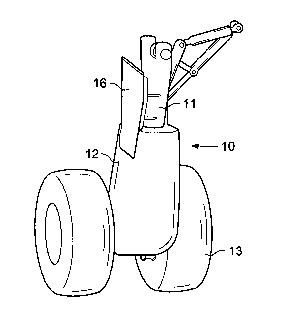
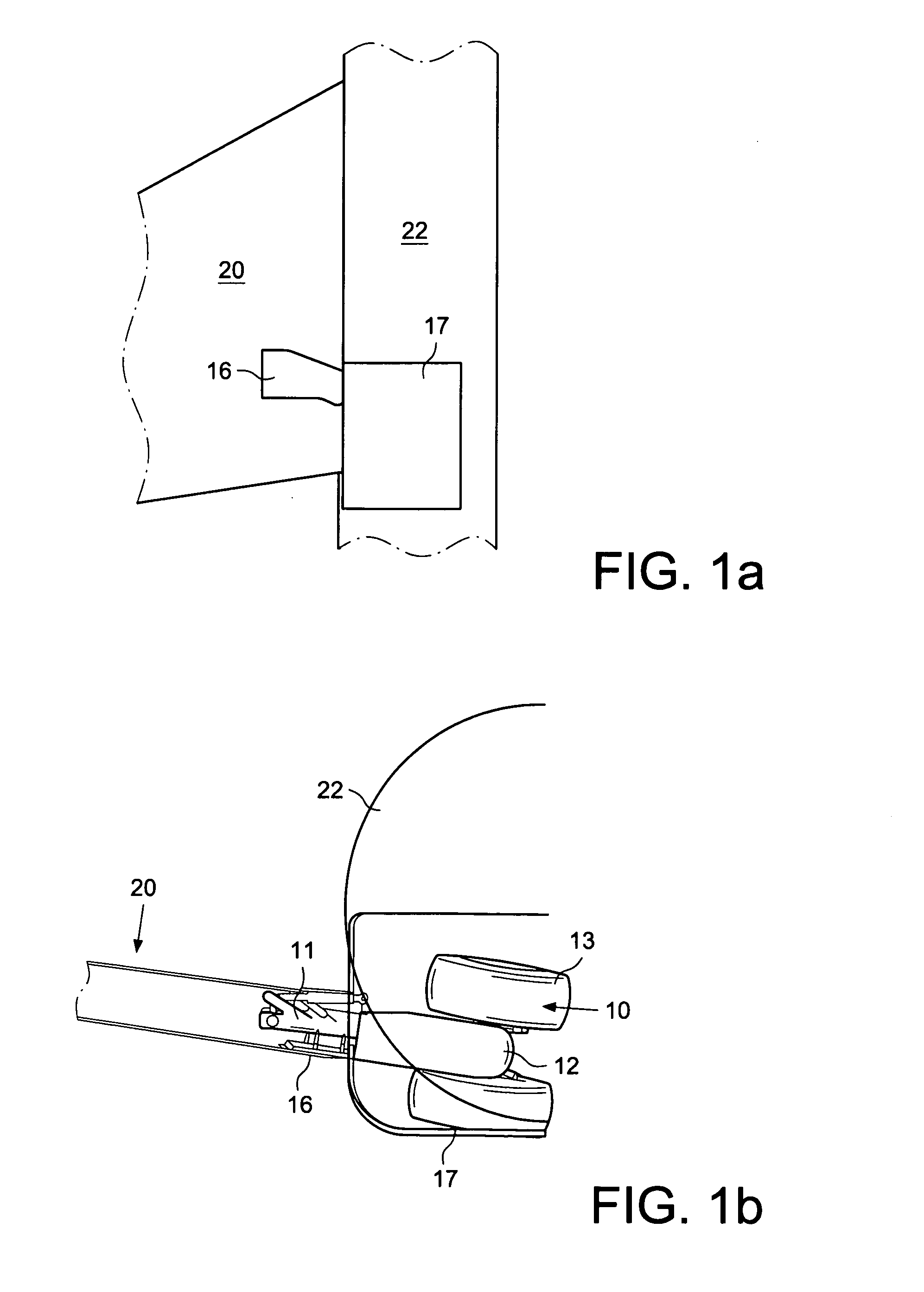
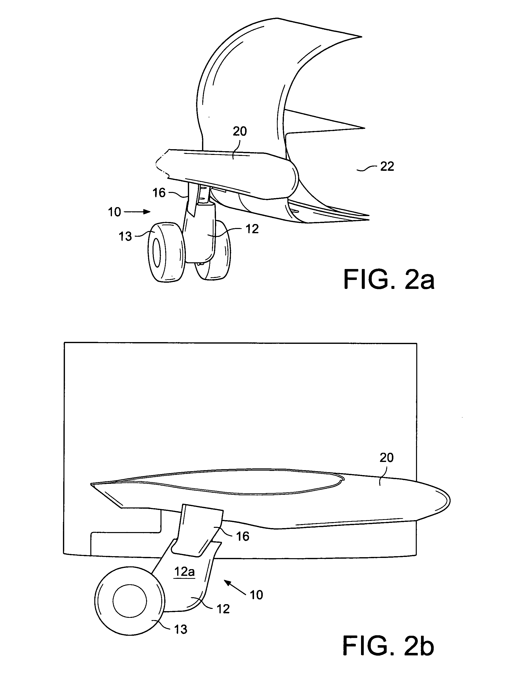
[0017]FIG. 1a shows a landing gear bay door assembly 16, 17 which forms part of the undercarriage assembly of an aircraft according to the first embodiment of the invention (FIG. 1a showing the closed doors when viewed from underneath the aircraft). The aircraft is of the type that has a wing-mounted landing gear 10 which is arranged to be moveable between a stowed position and a fully deployed position and which is of the short wing gear type having a trailing arm configuration. Inclusion of fairings for aerodynamic efficiency or for drag reduction is not therefore of importance, because the landing gear 10 will be stowed shortly after take-off. The aircraft includes a landing gear bay, which extends from the wing 20 to the fuselage 22. The landing gear bay door assembly thus includes a first door 16 which extends across part of a wing of the aircraft and a second door 17 which extends across part of the fuselage 22 of the aircraft. The doors 16, 17 are moveable to open or close th...


PUM


Abstract

An aircraft noise reduction apparatus is provided which includes an aircraft landing gear assembly and a noise reduction fairing 12. The landing gear assembly comprises a landing gear 10 arranged to be moveable between a stowed position and a fully deployed position. The noise reduction fairing 12 may comprise a wrap-around fairing which, when the landing gear 10 is in its fully deployed position, wraps around the landing gear 10 and extends along the majority of the length of a landing gear leg 11. A landing gear bay door assembly 16, 17 comprising at least one door may also be provided. The fairing 12 may have a recess 24 for accommodating one of landing gear bay doors when the door 16 is in its fully open position.

Description

[0001]The present invention relates to an aircraft landing gear and noise reduction assembly. More particularly, but not exclusively, the invention relates to an aircraft landing gear assembly designed to reduce the noise generated by the interaction of the landing gear and the air flowing past it during flight, landing and / or take-off.BACKGROUND OF THE INVENTION[0002]It is desirous to reduce the noise generated by aircraft, for example, to lessen disruption or inconvenience, resulting from aircraft noise, caused to the public on the ground near airports. A significant amount of noise is generated by the interaction of the aircraft and the air flowing past it, which results in turbulent flows and consequently noise. It is particularly important to reduce noise created during approach of the aircraft on landing. During approach, a significant contribution to the amount of noise that the aircraft generates is made by the landing gear, which is typically deployed early for landing for ...

Claims


Application Information

Patent Timeline
IPC IPC(8): B64C23/00B64C1/40B64C25/10
CPCB64C7/00B64C2025/003B64C25/001
Inventor CHOW, LEUNG CHOICAMPBELL, PHILIPWOOD, CHRISTOPHERDYER, ANDREW JOHN
Owner AIRBUS OPERATIONS LTD
Learn More