Anti-icing system and method for preventing ice accumulation

a technology of anti-icing system and anti-ice accumulation, which is applied in the direction of ohmic-resistance heating, transportation and packaging, chemistry apparatus and processes, etc., can solve the problems of ice formation on airfoils and other surfaces of aircraft structures, undesirable and/or dangerous flying conditions, and significant accumulation of ice within the engine and over exposed engine structures

Active Publication Date: 2010-06-24
MRA SYST LLC +1
View PDF12 Cites 34 Cited by
  • Summary
  • Abstract
  • Description
  • Claims
  • Application Information

AI Technical Summary

Benefits of technology

[0010]Another aspect is directed to a method for substantially prevent accumulation of ice on an aerodynamic surface. The method includes fabricating a composite structure including at least one composite layer, forming at least one heating element within the composite layer, and configuring the heating element to provide a transfer of heat to the aerodynamic surface.

Problems solved by technology

Aircraft, during flight and / or while on the ground, may encounter atmospheric conditions that cause the formation of ice on airfoils and other surfaces of the aircraft structure, including wings, stabilizers, rudder, ailerons, engine inlets, propellers, rotors, fuselage and the like.
Accumulating ice, if not removed, can add excessive weight to the aircraft and alter the airfoil configuration, causing undesirable and / or dangerous flying conditions.
More specifically, if engines are operated within icing conditions at low power for extended periods of time, ice accumulation within the engine and over exposed engine structures may be significant.
Over time, continued operation of the engine, a throttle burst from lower power operations to higher power operations, and / or vibrations due to either turbulence or asymmetry of ice accretion, may cause the accumulated ice build-up to be ingested by the high pressure compressor.
This sudden increase in aft stage corrected core speed may adversely impact compressor stall margin.
In some cases, it may also lead to an engine flame out.
Although pneumatic boots have been used on commercial aircraft and some light twin or small jet aircraft, the system, which requires an air compressor and vacuum system, is expensive and adds appreciable weight to light aircraft.
In each of these mechanical systems, boot operation affects the airfoil characteristics of the wing, with the result that the boots cannot be operated during landing or takeoff.
In addition to the drawbacks of the added weight and expense of current mechanical ice removal systems, each of these systems requires visual attention to the degree of ice build-up and careful timing of activation for maximum effectiveness.
Moreover, none of these systems are suitable for use as an anti-ice system (i.e. to prevent ice from forming).
Such an on-board chemical system may be costly to operate and rely on a finite supply of chemical during flight.
However, such systems are only usable where sufficient wattage is available to raise and / or maintain the temperature of the airfoil surface above the freezing point at typical aircraft speeds.
To achieve operational temperatures for such thermal systems, the power supply required to power a wire heating pad type anti-ice or de-ice system is significant, because of the inefficiencies of the resistive heating pad elements, and may not been a feasible alternative as anti-ice or de-ice systems for general aviation aircraft.

Method used


Image

  • Anti-icing system and method for preventing ice accumulation
  • Anti-icing system and method for preventing ice accumulation
  • Anti-icing system and method for preventing ice accumulation

Examples


Embodiment Construction

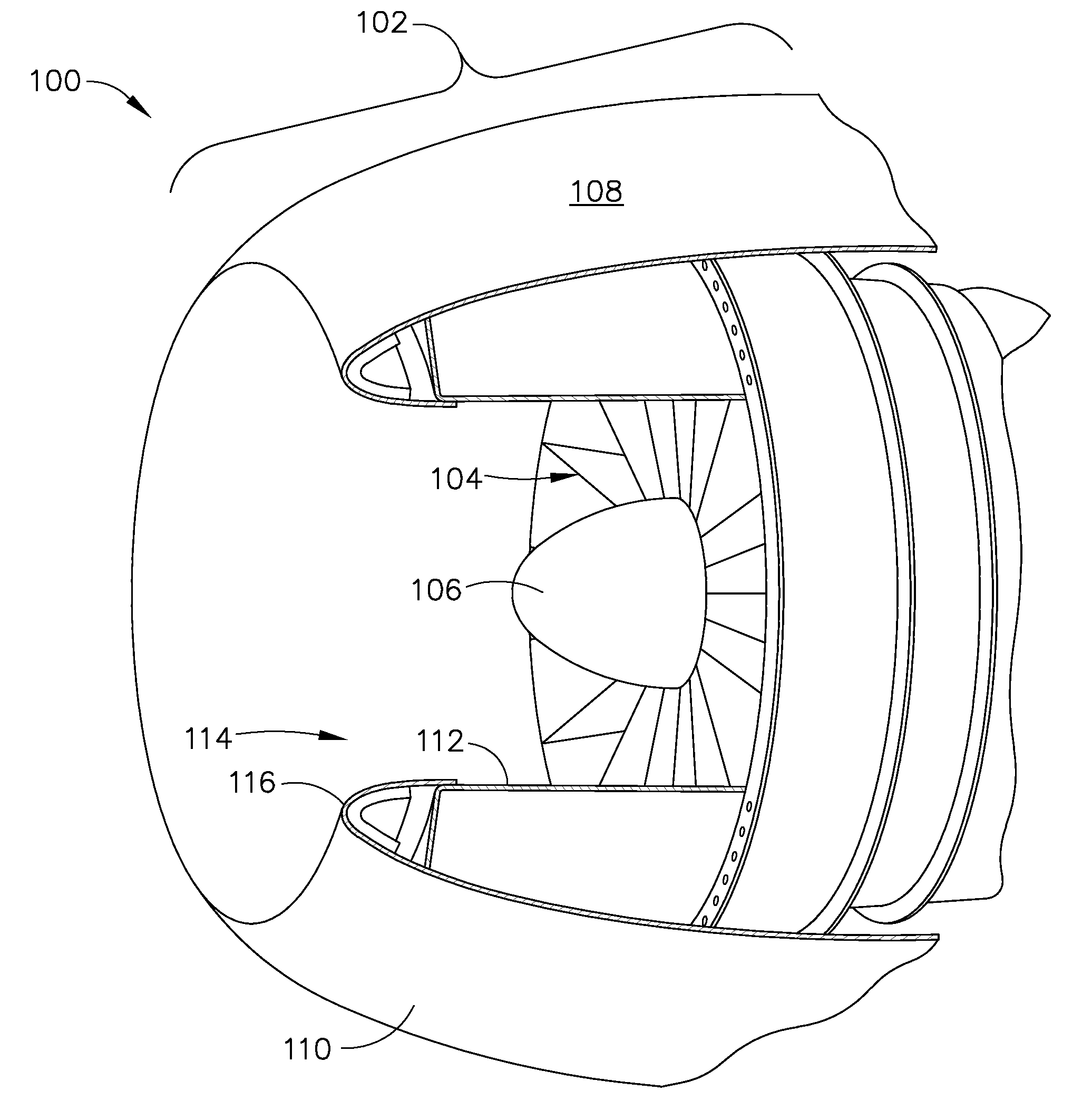
[0019]FIG. 1 is a cross-sectional view of a portion of turbine engine 10. In the exemplary embodiment, turbine engine 10 includes a fan assembly 16 that is rotatably coupled about a longitudinal centerline axis 32. In the exemplary embodiment, fan assembly 16 is positioned at a forward end 33 of turbine engine 10. In an alternative embodiment, fan assembly 16 is positioned at an aft end 35 of turbine engine 10. Fan assembly 16 includes a plurality of rows of fan blades 19 positioned within a nacelle assembly 12. In one embodiment, nacelle assembly 12 houses various operating components (not shown) of turbine engine 10.

[0020]In the exemplary embodiment, turbine engine 10 also includes a core engine 17 that is positioned downstream from fan assembly 16. Core engine 17 includes a compressor 18, a combustor 20, and a turbine 22 that is coupled to compressor 18 via a core rotor shaft 26.

[0021]During operation, core engine 17 generates combustion gases that are channeled downstream to a t...


PUM

PropertyMeasurementUnit
conductiveaaaaaaaaaa
electrical voltageaaaaaaaaaa
aerodynamicaaaaaaaaaa

Abstract

An anti-icing system includes a component surface having a composite structure including a composite layer, and at least one heating element formed within the composite layer, wherein the heating element is configured to provide a transfer of heat to the component surface.

Description

BACKGROUND OF THE INVENTION[0001]The field of the disclosure relates generally to aircraft anti-icing systems, and more specifically to a system for electrically preventing the accumulation of ice build-up on leading edge surfaces.[0002]Gas turbine engines typically include an inlet, a fan, low and high pressure compressors, a combustor, and at least one turbine. The compressors compress air which is channeled to the combustor where it is mixed with fuel. The mixture is then ignited for generating hot combustion gases. The combustion gases are channeled to the turbine(s) which extracts energy from the combustion gases for powering the compressor(s), as well as producing useful work to propel an aircraft in flight or to power a load, such as an electrical generator.[0003]Aircraft, during flight and / or while on the ground, may encounter atmospheric conditions that cause the formation of ice on airfoils and other surfaces of the aircraft structure, including wings, stabilizers, rudder,...

Claims


Application Information

Patent Timeline
Patent Type & Authority Applications(United States)
IPC IPC(8): B64D15/12B64D15/00
CPCB64D15/12B64D2033/0233H05B3/145H05B3/347H05B2203/033H05B2203/013H05B2203/014H05B2203/017H05B2203/005
Inventor CALDER, DAVID P.HOWARTH, GRAHAM
Owner MRA SYST LLC
Why Eureka
Try Eureka