Device for measuring the current flowing through a power transistor of a voltage regulator

a technology of voltage regulator and power transistor, which is applied in the direction of electrical equipment, electric variable regulation, instruments, etc., can solve the problems of large measurement error, inability to reduce error, and inability to adapt to technology

Active Publication Date: 2010-06-24
STMICROELECTRONICS SRL
View PDF8 Cites 15 Cited by
  • Summary
  • Abstract
  • Description
  • Claims
  • Application Information

AI Technical Summary

Benefits of technology

[0012]In accordance with another aspect of the foregoing embodiment, the circuit block further includes a comparison circuit coupled to the circuit block that compares the output current of the circuit block with a reference current and generates in response to the comparison a signal used to drive the power transistor to control current flowing through the power transistor.

Problems solved by technology

This technology is not adapted to the voltage regulators wherein the power MOS transistor M1 has a small on resistance and is capable of providing currents on the order of the Ampere.
For this reason the mirror rate is not constant, and this introduces a large error on the measurement.
This error cannot be reduced by using a small resistance Rs because the error amplifier has a limited sensitivity.

Method used


Image

  • Device for measuring the current flowing through a power transistor of a voltage regulator
  • Device for measuring the current flowing through a power transistor of a voltage regulator
  • Device for measuring the current flowing through a power transistor of a voltage regulator

Examples


Embodiment Construction

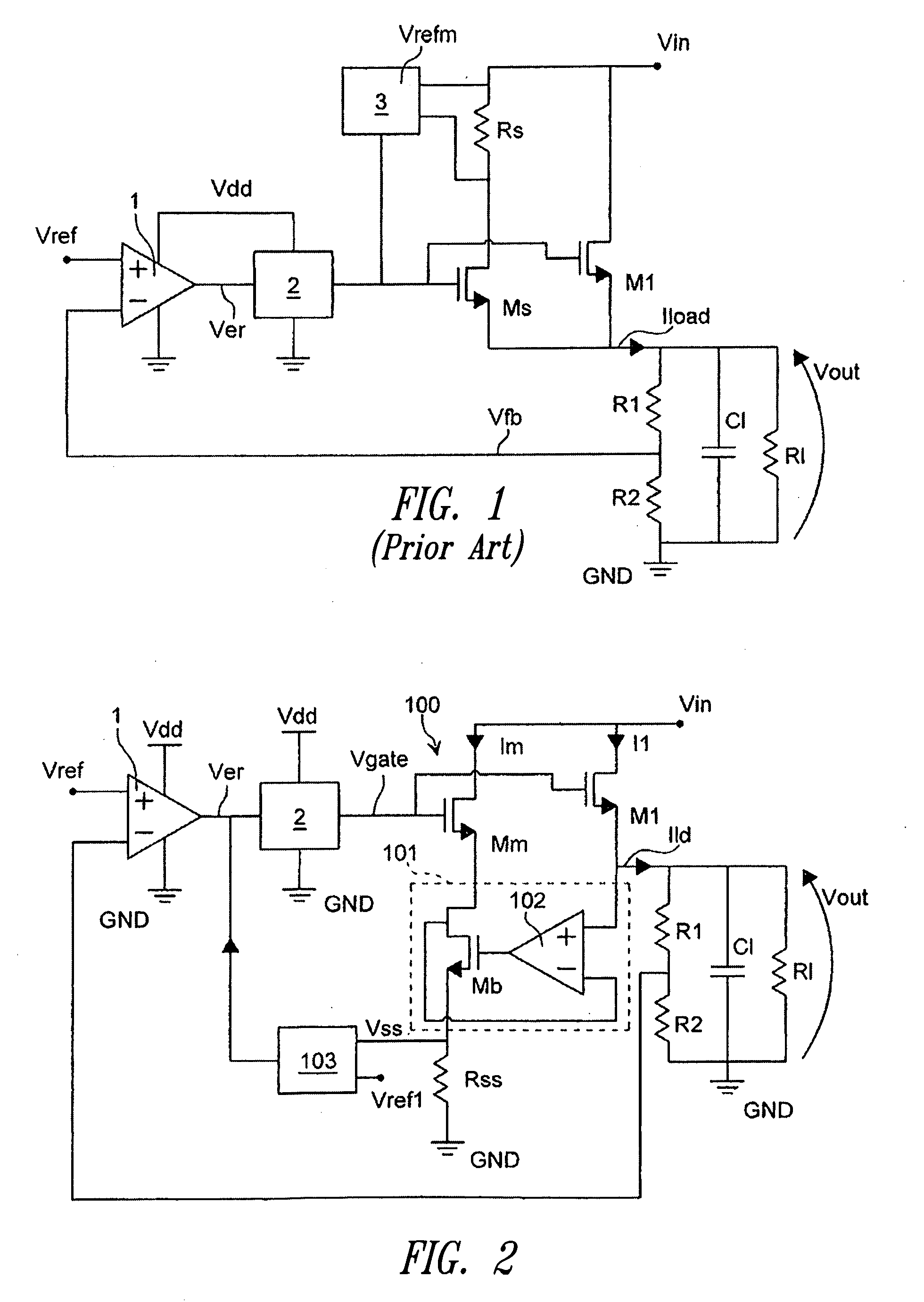
[0019]For the sake of convenience, reference numbers common to elements of FIG. 1 are used throughout the remaining figures.

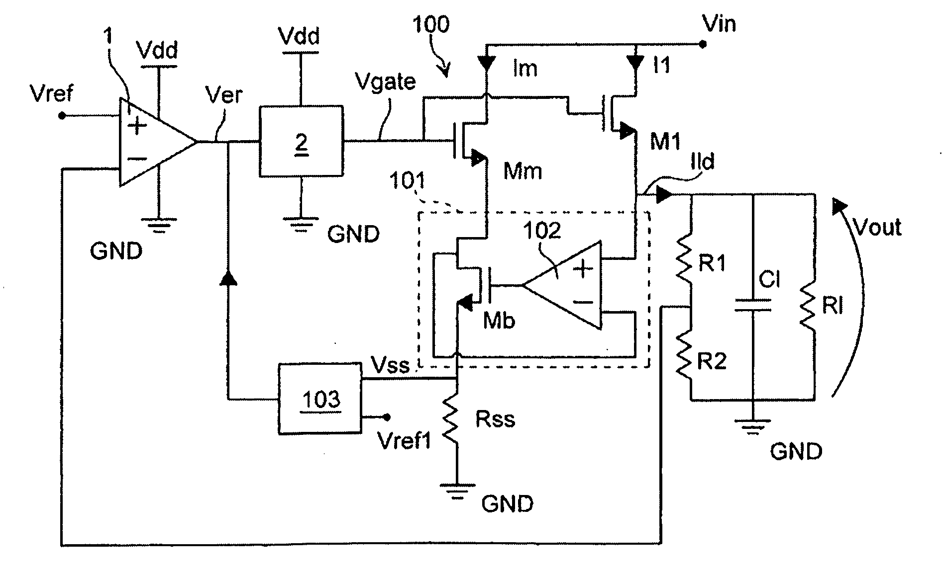
[0020]FIG. 2 is a schematic view of a device for measuring the current flowing through a power transistor of a voltage regulator according to an embodiment of the present disclosure. The voltage regulator in FIG. 2 includes a MOS power transistor M1 having a drain terminal coupled with an input voltage Vin and a source terminal connected with one terminal of a capacitor CI, connected in parallel to a resistance RI, and having the other terminal connected to ground GND; the output voltage Vout is present across the terminals of the capacitor CI. A voltage divider constituted by two resistance R1 and R2 is arranged parallel to the capacitor CI so that the voltage Vfb, which is a portion of the voltage Vout, is at the input inverting terminal of an error amplifier 1, which has the reference voltage Vref at the input non-inverting terminal. The error amplifier 1 is...


PUM


Abstract

A device for measuring the current flowing through a power transistor of a voltage regulator, the voltage regulator having an input voltage and providing a regulated output voltage and the power transistor coupled between the input and output voltages. The measuring device includes a further transistor adapted to mirror a portion of the current flowing through the power transistor, the further transistor and the power transistor have a first non-drivable terminal in common that is coupled to the input voltage. The measuring device also includes a circuit block to connect the second non-drivable terminals of the power and the further transistor and to provide an output current equal to the portion of the current flowing through the first transistor; the measuring device further including a circuit adapted to detect the output current of said circuit block.

Description

BACKGROUND[0001]1. Technical Field[0002]The present disclosure refers to a device for measuring the current flowing through a power transistor of a voltage regulator.[0003]2. Description of the Related Art[0004]The use of a device to measure a current flowing through a MOS power transistor connected between the non-regulated input voltage and the regulated output voltage is known in the state of the art; the measurement effectuated by the device allows to limit the current flowing through the power MOS transistor.[0005]A linear voltage regulator according to a prior design is shown in FIG. 1. The regulator includes a MOS power transistor M1 having the drain terminal coupled with an input voltage Vin and the source terminal connected with one terminal of a capacitor CI, connected in parallel to a resistance RI, and having the other terminal connected to ground GND; the output voltage Vout is present across the terminals of the capacitor CI. A voltage divider constituted by two resist...

Claims


Application Information

Patent Timeline
Patent Type & Authority Applications(United States)
IPC IPC(8): G05F1/00G01R19/00
CPCG01R19/16552H03K2217/0081H03K17/0822G05F1/573
Inventor MARINO, FILIPPOMINIERI, MARCOPETRINA, GAETANO
Owner STMICROELECTRONICS SRL
Why Eureka
Try Eureka