Metering skive for a developer roller

a technology of developer rollers and metering skives, which is applied in the direction of electrographic process equipment, instruments, optics, etc., can solve the problems of increasing cohesion, achieve the effects of reducing the compression of the developer, minimizing the compression of the metered developer, and promoting shearing of the developer

Inactive Publication Date: 2010-06-24
EASTMAN KODAK CO
View PDF12 Cites 5 Cited by
  • Summary
  • Abstract
  • Description
  • Claims
  • Application Information

AI Technical Summary

Benefits of technology

[0010]The present invention further relates to a metering skive adapted to meter a flow of developer that is supplied onto a surface of a developer roller which comprises a first surface located on an exit side of the metering skive with respect to a direction of developer flow onto a surface of a developer roller; and a second surface located on an entrance side of the metering skive with respect to the direction of developer flow onto the surface of the developer roller, with the second surface being a curved surface. The metering skive is located at a position relative to the surface of the developer roller where the first surface of the metering skive is at an angle from the tangent line that defines a 45 degree shear angle; and the second curved surface defines a radius which is sized to hold a portion of developer that is sheared from the developer roller surface by the metering skive, such that the metering skive is adapted to meter the developer flow while minimizing compression of the metered developer on the surface of said developer roller.
[0011]In a feature of the present invention, developer compression induced by the metering process is reduced with a metering skive geometry that is adapted to promote shearing of the developer at a developer-skive interface, wherein the metering skive forms a pointed tip or edge at the developer-skive interface. Specifically, compression is minimized or reduced when the angle of a first surface of the metering skive is between 0 degrees and 90 degrees relative to the tangent line of the developer roller, preferably between 45 degrees and 90 degrees relative to the tangent of the developer roller, and more preferably 45 degrees. This allows for extra flow to be shed from the raw flow without effecting the compression of the raw flow, and also prevents any additional post metering compression of the metered flow. In a further feature of the present invention, the metering skive includes a second surface that has a curvature and a generous radius on an entrance side of the skive with respect to a direction of developer flow, to facilitate shedding and / or capture of the extra flow.

Problems solved by technology

Excessive compression by a metering skive or doctor blade will cause the bulk density of the developer to approach its true density, causing failure as the developer forms ‘sheets’ when it reaches its maximum density and exits the development station, since developer cohesiveness increases with increasing bulk density.

Method used


Image

  • Metering skive for a developer roller
  • Metering skive for a developer roller
  • Metering skive for a developer roller

Examples


Embodiment Construction

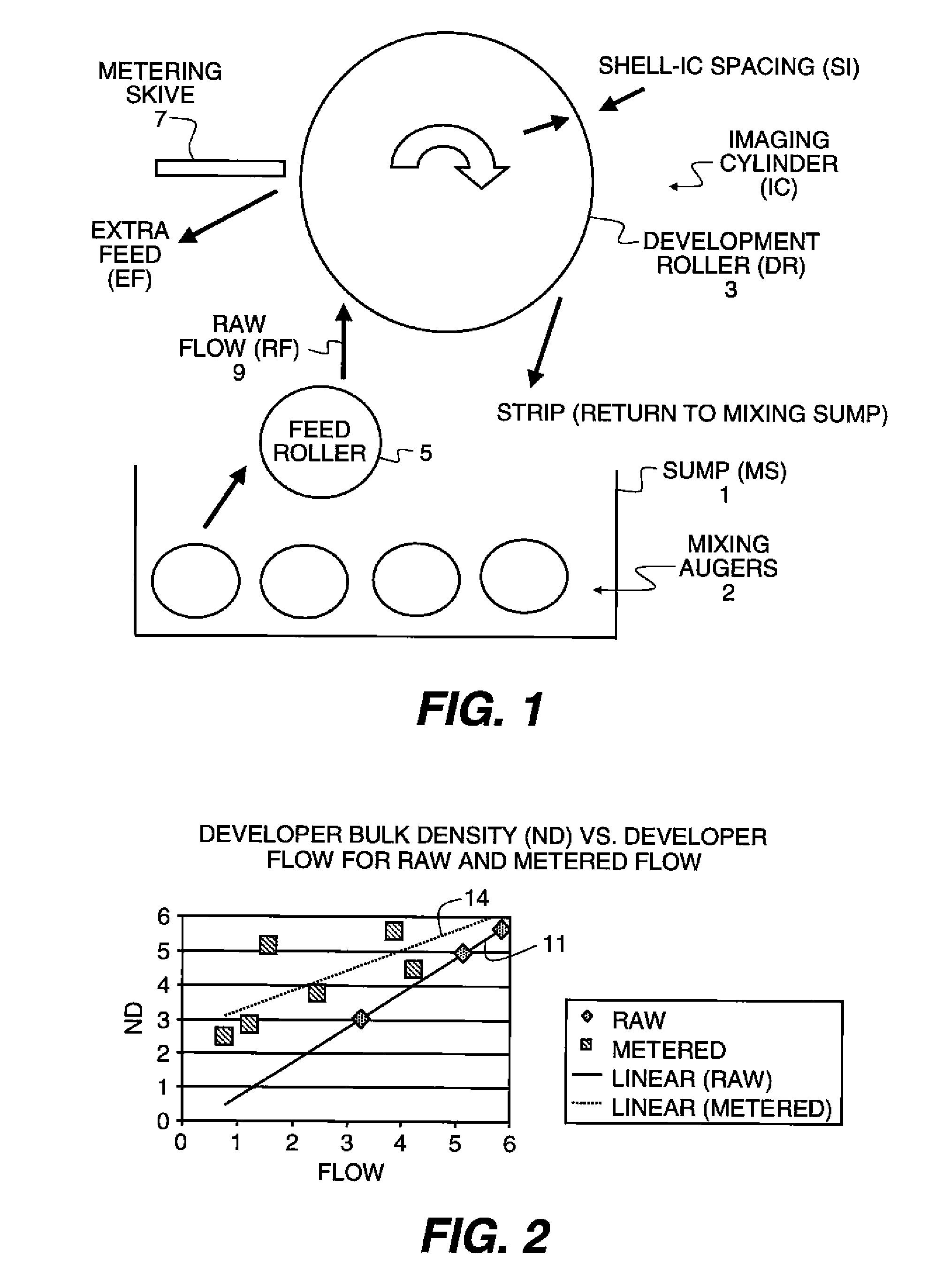
[0022]Referring now to the drawings, wherein like reference numerals represent identical and / or corresponding parts throughout the several views, an embodiment of a development station or development system is shown in FIG. 1. In this embodiment, a 2-Component developer is replenished with new toner, thoroughly mixed in a mixing sump 1 having mixing augurs 2, and transported to a development or developer roller 3 by means of a rotating feed roller 5. Feed roller 5 is adapted to act as a buffer between turbulent flow in the mixing sump 1 and the more controlled, smooth flow necessary for the development process. A mechanical doctor blade or metering skive 7 is then used to further reduce flow variations in the developer flow along the length of the development roller 3. This necessitates that raw flow 9 (RF) (which is developer introduced onto the development roller 3 from the feed roller 5) is greater than metered flow (MF) (which is a desired final flow after the skiving process). ...


PUM


Abstract

A metering skive for a developer roller which is adapted to shear and/or meter developer at a developer-skive interface while minimizing compression of the metered developer. The metering skive is adjustable to various shear angles and has a geometry which enables a portion of the developer flow to be sheared away toward a curved second surface of the metering skive while metering the developer flow in a manner which minimizes or reduces compression of the developer.

Description

FIELD OF THE INVENTION[0001]The present invention relates to a metering skive for a developer roller which is adapted to shear or meter developer at a developer-skive interface while minimizing compression of the metered developer.BACKGROUND OF THE INVENTION[0002]In a two component development system, the ability to apply sufficient developer (toner+carrier) to develop a latent image on a photoconductor enables the creation of images with high fidelity and quality. In general practice, developer “Flow” is the common metric used to describe the amount of developer delivered to a toning zone per unit time. This is accomplished by lowering a gate into a developer stream, (2″ wide) and collecting developer for a specified amount of time (0.5 Sec). This developer is then weighed and reported in units of gm / in / s. This has been correlated against certain imaging properties of the developer, such as toning contrast, background, etc.[0003]Since the measurement of developer flow aggregates th...

Claims


Application Information

Patent Timeline
Patent Type & Authority Applications(United States)
IPC IPC(8): G03G15/08
CPCG03G15/0812
Inventor BROWN, KENNETH J.KEPNER, DAVID S.
Owner EASTMAN KODAK CO
Why Eureka
Try Eureka