Methods for Identifying Areas of a Subject's Skin that Appear to Lack Volume

Inactive Publication Date: 2010-06-24
IPSYRNG CAPITAL DEV
View PDF11 Cites 11 Cited by
  • Summary
  • Abstract
  • Description
  • Claims
  • Application Information

AI Technical Summary

Benefits of technology

[0006]In some aspects, the present disclosure provides techniques for identifying areas in a subject that are under volume. In some aspects, this can be used for the administrat

Problems solved by technology

Despite the fact that such methods are being used with ever increasing frequency, the art has

Method used


Image

  • Methods for Identifying Areas of a Subject's Skin that Appear to Lack Volume
  • Methods for Identifying Areas of a Subject's Skin that Appear to Lack Volume
  • Methods for Identifying Areas of a Subject's Skin that Appear to Lack Volume

Examples


example 1

Grid Application

[0125]This example generally outlines how one can apply an injectable filler composition using one embodiment of the dynamic grid. The subject will flex a first muscle group that pulls a section of skin in a first manner. Wrinkles and lines that are visible in the section of skin in the first flexed position will be identified. This can be achieved by tracing the wrinkle or line on the subject's skin with a marker. The subject will then flex a second muscle group. This second muscle group will pull the section of skin in an opposing direction to that pulled by the first muscle group. The wrinkles and / or lines that are visible in the second flexed position will be identified via tracing the wrinkle or line on the subject's skin with a marker. A dermal filler will then be injected into the subject according to where the first markings and second markings intersect. As sufficient amount of dermal filler will be injected so that the first, second, or both lines or wrinkl...

example 2

Grid Application, Lower Face

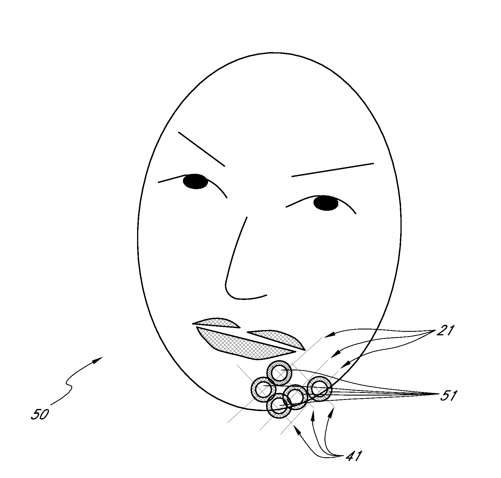
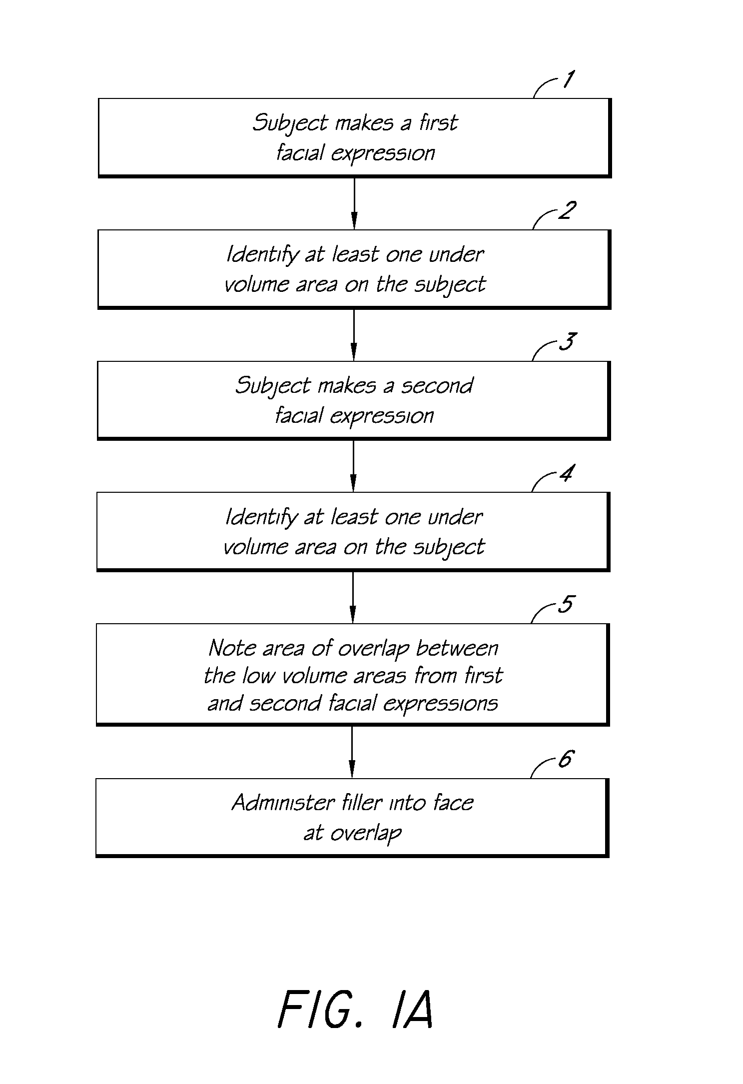
[0127]This example describes how one can apply an injectable filler composition to the lower face of a subject using a dynamic grid technique. The subject will sit up during the injection. The subject will make a first facial expression. The lines / wrinkles, etc. that are observable in the first facial expression in the lower face will be marked on the subject's lower face using washable ink. The subject will then make a second facial expression and the lines / wrinkles, etc. that are observable in the second facial expression will also be marked on the subject's lower face. The facial expressions can include a smile, lip pucker, frown, etc. The markings from the first and second facial expressions will intersect at, at least one intersection point. One will then inject a dermal filler by placing boluses of the filler according to the line intersects. These injections can be supra-periosteal (inserting the needle at a 90 degree angle to face).

[0128]One can t...

example 3

Grid Application, Upper Face

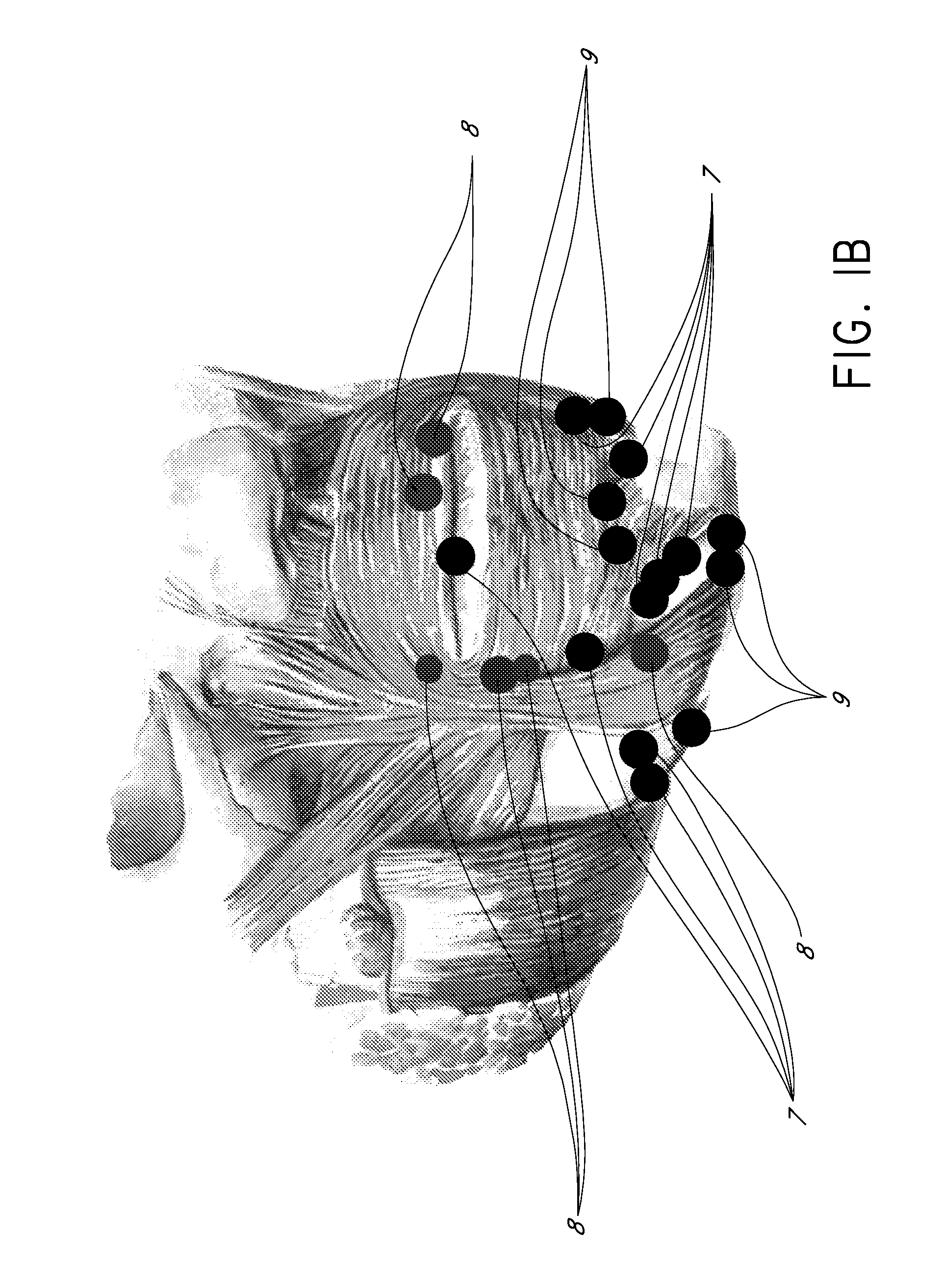
[0133]This example describes how one can apply an injectable filler composition to the upper face of a patient using a dynamic grid technique. The subject will sit up during the injection. The subject will make a first facial expression. The lines / wrinkles, etc. that are observable in the first facial expression will be marked on the subject's upper face via washable ink. The subject will then make a second facial expression and the lines / wrinkles, etc. that are observable in the second facial expression will also be marked on the subject's upper face. The facial animations can include a smile, lip pucker, frown, etc. One will then inject an injectable filler composition by placing boluses of the filler according to the markings created during the two facial expressions intersect. These injections can be supra-periosteal (inserting the needle at a 90 degree angle to face).

[0134]One can then inject using threading, bolus, and / or serial puncture at areas no...


PUM

PropertyMeasurementUnit
Fractionaaaaaaaaaa
Volumeaaaaaaaaaa
Volumeaaaaaaaaaa

Abstract

The present embodiments relate to methods and systems for identifying areas of a subject's skin that lack sufficient volume. In some embodiments, this can be used to direct the administration of filler compositions or the application of techniques that increase the volume or firmness of the area. In some embodiments, the methods and systems provide for improved aesthetic benefit as well as suitability for instruction and training. In some embodiments, the methods are especially useful in the administration of dermal fillers to a subject.

Description

RELATED APPLICATIONS[0001]This application claims priority to U.S. Provisional Application No. 60 / 938,424, filed May 16, 2007, and U.S. Provisional Application No. 60 / 938,425, filed, May 16, 2007, each of which is herein incorporated by reference in their respective entireties.BACKGROUND[0002]1. Field of the Invention[0003]Methods and systems relating to the identification of areas that are under volume in a subject's skin are provided.[0004]2. Description of the Related Art[0005]Methods for delivery or injection of fillers into a subject or subject's face for cosmetic purposes are well-known. Despite the fact that such methods are being used with ever increasing frequency, the art has seen little in the way of developments in regard to certain aspects of these injection methods.SUMMARY[0006]In some aspects, the present disclosure provides techniques for identifying areas in a subject that are under volume. In some aspects, this can be used for the administration of injectable fille...

Claims


Application Information

Patent Timeline
IPC IPC(8): A61B5/103A61M5/178A61N1/00
CPCA61K31/18A61K38/4886A61K38/39A61K31/728
Inventor BARBOUR, JENNIFER
Owner IPSYRNG CAPITAL DEV
Why Eureka
Try Eureka