Ejector-type refrigerant cycle device
a refrigerant cycle and ejector technology, which is applied in the direction of refrigeration machines, refrigeration components, lighting and heating apparatus, etc., can solve the problems of reducing reducing the recovery energy, and reducing the refrigerant so as to reduce the suction capacity of the ejector, reduce the improvement effect of the cop, and reduce the recovery energy
- Summary
- Abstract
- Description
- Claims
- Application Information
AI Technical Summary
Benefits of technology
Problems solved by technology
Method used
Image
Examples
1st embodiment
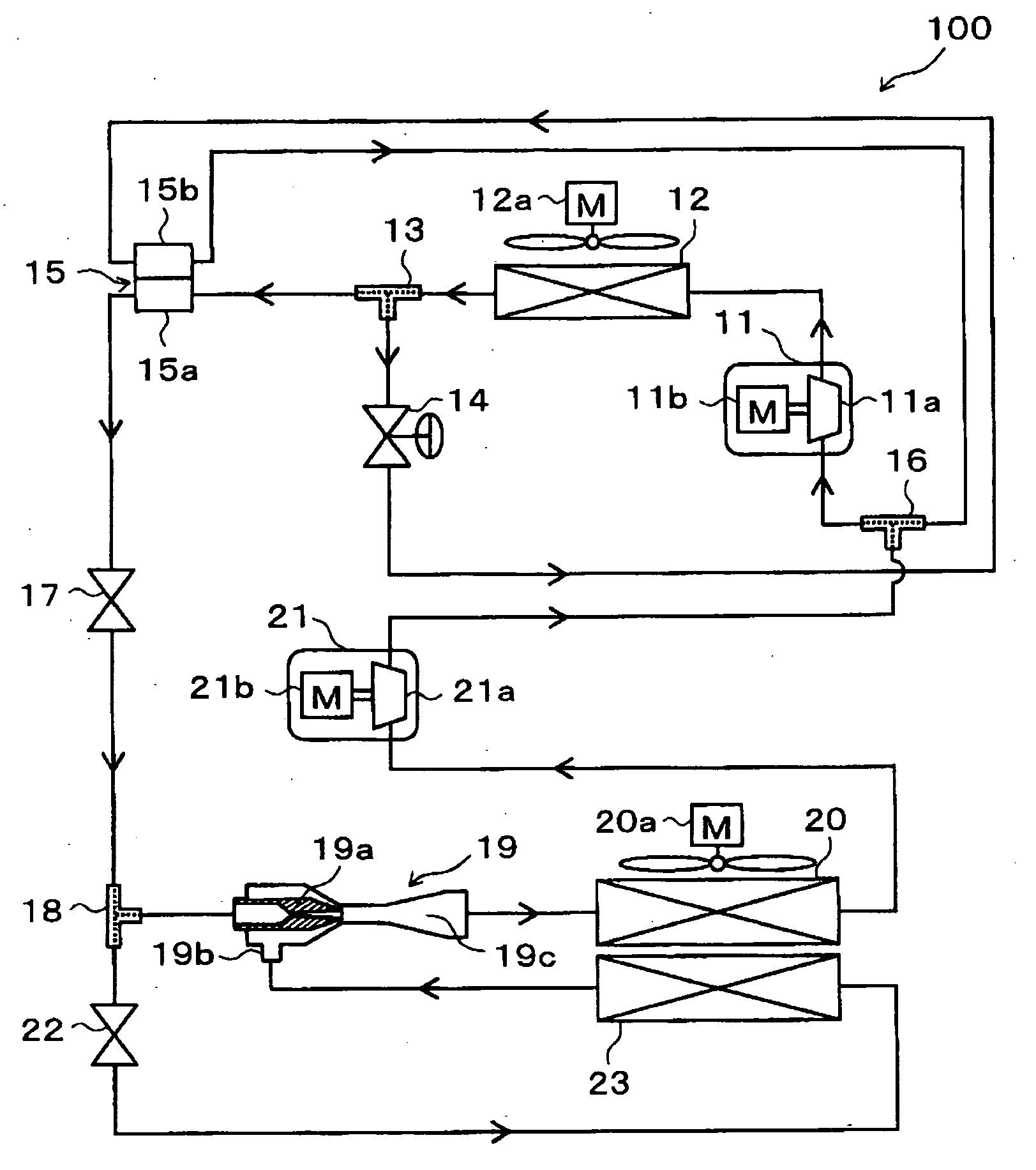
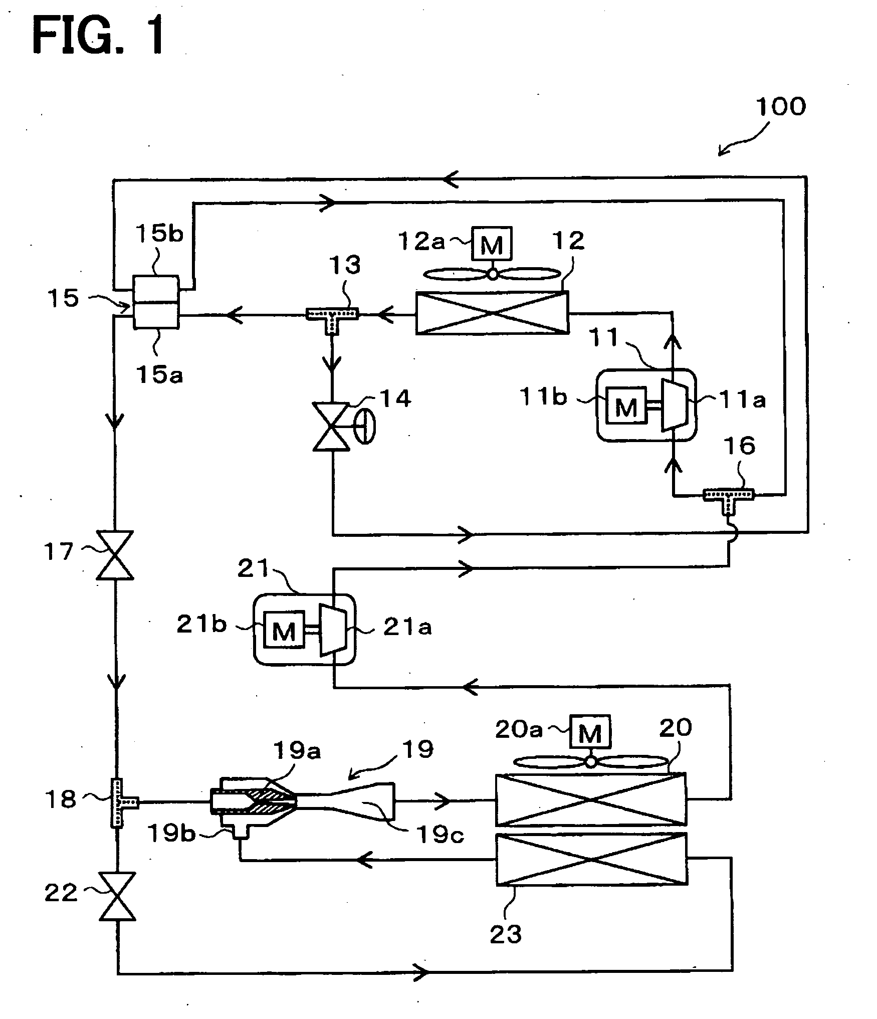
[0319]An ejector-type refrigerant cycle device 100 of the present invention, adapted as a refrigerator, will be described with reference to FIGS. 1 and 2. The refrigerator is for cooling a refrigerating interior room, that is a space to be cooled, to an extremely low temperature such as in a range between −30° C. and −10° C. FIG. 1 is an entire schematic diagram of the ejector-type refrigerant cycle device 100 of the present embodiment.
[0320]In the ejector-type refrigerant cycle device 100 of the present embodiment, a first compressor 11 is configured to draw refrigerant, to compress the drawn refrigerant, and to discharge the compressed refrigerant. For example, the first compressor 11 is an electrical compressor in which a first compression portion 11a having a fixed displacement is driven by a first electrical motor 11b. As the first compression portion 11a, various compressors such as a scroll type compressor, a vane type compressor and a rotary-piston type compressor can be use...
2nd embodiment
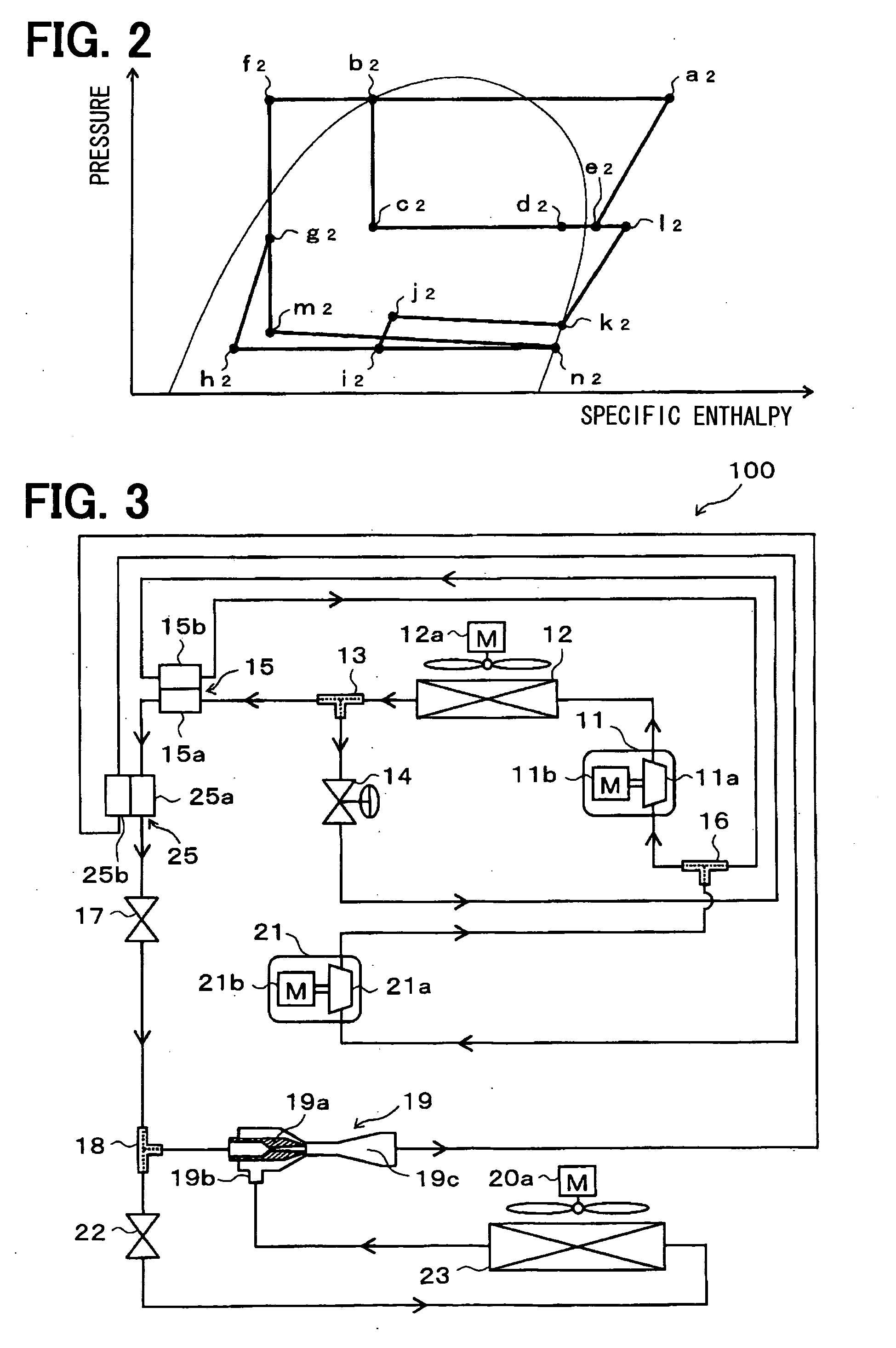
[0377]As shown by the entire schematic diagram of FIG. 3, the present embodiment describes regarding an example in which an auxiliary inner heat exchanger 25 is added and the discharge side evaporator 20 is removed, with respect to the ejector-type refrigerant cycle device 100 of the 1st embodiment. In the example of FIG. 3, the same parts or corresponding parts with the 1st embodiment are indicated by the same reference numbers. The following figures are indicated by the same way.
[0378]The basic structure of the auxiliary inner heat exchanger 25 of the present embodiment is the same as that of the inner heat exchanger 15 of the 1st embodiment. The auxiliary inner heat exchanger 25 is configured to perform heat exchange between the refrigerant passing through a high-pressure side refrigerant passage 25a, having passed through the inner heat exchanger 15 from the first branch portion 13, and the refrigerant passing through a low-pressure side refrigerant passage 25b, from the diffuse...
3rd embodiment
[0385]As shown by the entire schematic diagram of FIG. 5, the present embodiment describes regarding an example in which an auxiliary radiator 24 is added, with respect to the ejector-type refrigerant cycle device 100 of the 1st embodiment. The auxiliary radiator 24 is a heat-radiating heat exchanger in which the high-pressure refrigerant flowing from the first branch portion 13 toward the inner heat exchanger 15 is heat exchanged with air (outside air) outside of the room, blown by the cooling fan 12a, thereby further cooling the high-pressure refrigerant.
[0386]In FIG. 5, the cooling fan 12a is located near the radiator 12 for easily indicating in the figure, however, the cooling fan 12a is configured to blow the outside air to not only the radiator 12 but also to the auxiliary radiator 24. The radiator 12 and the auxiliary radiator 24 may be configured to blow air outside the room of the refrigerator by using respectively independent blower fans.
[0387]The radiator 12 of the presen...
PUM
 Abstract
Description
Claims
Application Information
 - R&D
- Intellectual Property
- Life Sciences
- Materials
- Tech Scout
- Unparalleled Data Quality
- Higher Quality Content
- 60% Fewer Hallucinations
Browse by: Latest US Patents, China's latest patents, Technical Efficacy Thesaurus, Application Domain, Technology Topic, Popular Technical Reports.
© 2025 PatSnap. All rights reserved.Legal|Privacy policy|Modern Slavery Act Transparency Statement|Sitemap|About US| Contact US: help@patsnap.com


