Tube for fixation and method of producing same

a technology for fixing tubes and tubes, applied in the field of producing tubes for fixing, can solve the problems of not divulging technical means in the early arts, and achieve the effects of increasing the surface area of the tube, good workability, and raising the fatigue strength

Inactive Publication Date: 2010-07-01
ENDO MFG COMPANY
View PDF8 Cites 5 Cited by
  • Summary
  • Abstract
  • Description
  • Claims
  • Application Information

AI Technical Summary

Benefits of technology

[0009]An object of the present invention is to provide a tube for fixation adapted for plastic formed parts by drawing and a method for producing the same, wherein the residual compression stress is increased prior to coating the metal original form, which is the original form of the tube for fixation, with coating material so as to prevent metallic fatigue of the drawn plastic formed parts and extend its lifetime and the surface is roughened to improve the coating properties, that is, the adhesiveness of the coating material.
[0023]In the ninth aspect of the invention, the tube for fixation according to the eighth aspect is further characterized in that as to the imparting of residual compression stress and the roughening, sandblasting of roughening the surface and imparting residual compression stress to the surface are performed by projecting abrasive material made of alumina (Al2O3) material with a blast size No. 220 to 400 at a projection pressure of 0.098 to 0.39 MPa (1 to 4 kgf / cm2) so as to roughen the surface and impart residual compression stress to the surface.
[0025]The tube for fixation and the method for producing the same according to the present invention involve sandblasting to the surface of a cylindrical metal body with good workability which has been molded to be a thin body by means of plastic working by drawing and then performing a coating process, thereby producing the tube for fixation. Hence, residual compression stress is imparted to the tube for fixation by means of this process in order to raise the fatigue strength, while the surface area of the tube is increased by roughening of the surface thereof. As a result, it is possible to produce a tube for fixation which has stable strength and increased reliability in adhesiveness of coating material without probability of peeling of the coating layer even under harsh conditions in use such as with heating.

Problems solved by technology

However, problems such as peeling of the coating material from the photosensitive drum should not occur no matter how harsh the environment in use may be.
However, the prior arts do not disclose the technical means which solve the problems mentioned above by processing which is effective when the metal original form is a plastic formed part by drawing.

Method used


Image

  • Tube for fixation and method of producing same
  • Tube for fixation and method of producing same
  • Tube for fixation and method of producing same

Examples


Embodiment Construction

[0035]An embodiment of the tube for fixation and the method for producing the same of the present invention will now be explained, including Examples which show experiment results.

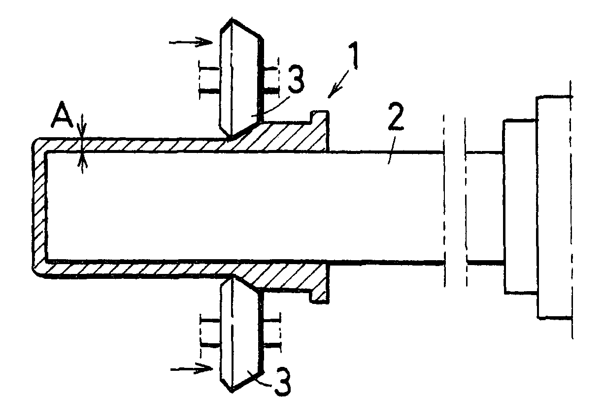
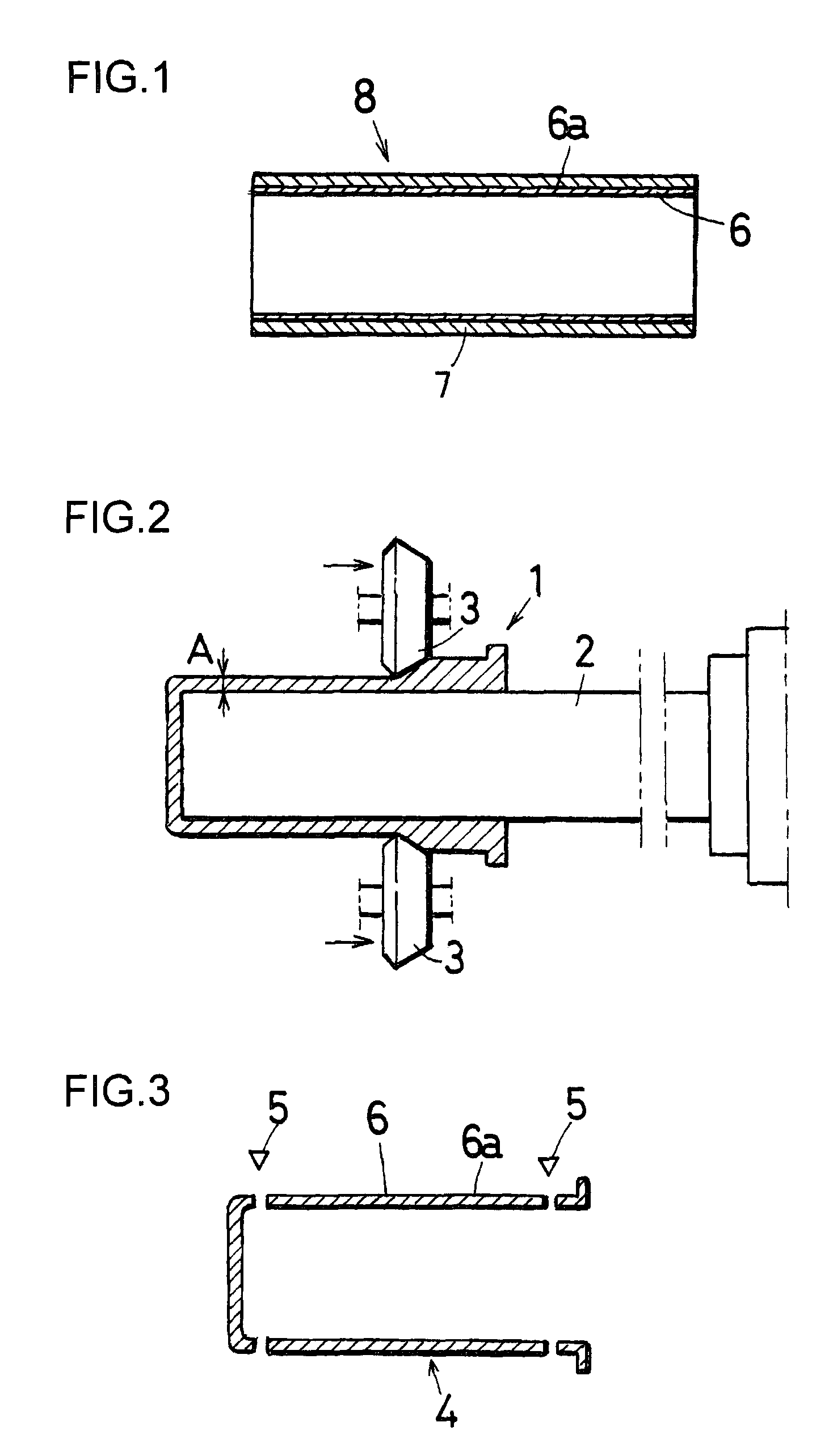
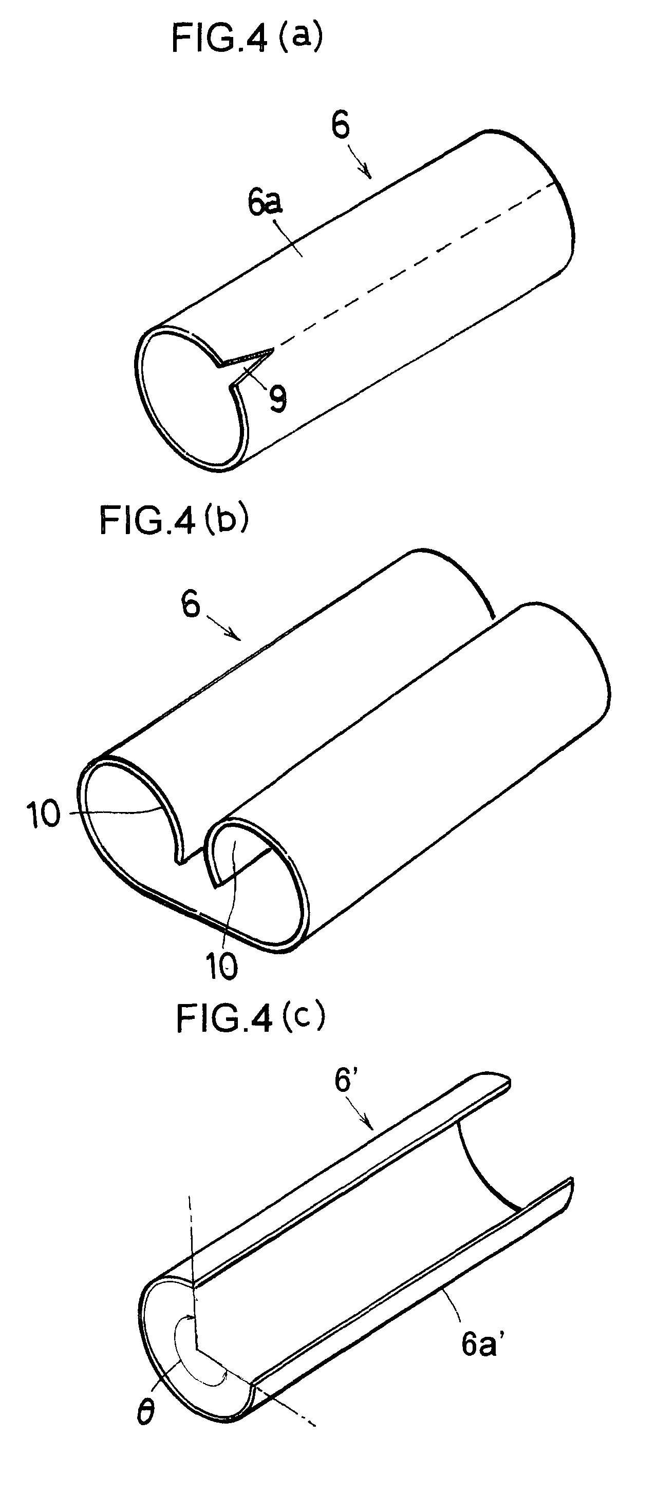
[0036]FIG. 1 is a cross-sectional view of a tube for fixation which shows the constitution of the present invention; FIG. 2 is an explanatory diagram showing an arrangement of forming a metal original form by spinning; FIG. 3 is an explanatory diagram showing an arrangement in which a metal original form which has undergone forming by spinning is cut to obtain a metal tube; FIGS. 4A and 4B show deformed states when a metal tube which has undergone sandblasting is cut, where FIG. 4A is a perspective view indicating the cutting position, FIG. 4B is a perspective view of the deformed state of the metal tube after cutting, and FIG. 4C is a perspective view of the deformed state of a metal tube produced by the prior art after the metal tube has been cut. FIG. 5 is an explanatory diagram showing an arrangement i...


PUM

PropertyMeasurementUnit
thicknessaaaaaaaaaa
pressureaaaaaaaaaa
pressureaaaaaaaaaa

Abstract

A tube for fixation, which has increased durability and a method of producing the same are provided.Forming by spinning is carried out so as to thin the thickness A of a side wall of a bottomed prime tube 1 of a plastically deformable metal to a thickness of 20 to 50 μm while rotating the bottomed prime tube 1 about the axis thereof and a metal original form 4 is formed. The metal original form 4 formed by spinning is cut to form a metal tube 6. The surface 6a of the metal tube 6 is sandblasted to impart residual compression stress to the surface 6a and to roughen the same. The treated surface is covered with a fluorocarbon resin film 7. The fluorocarbon resin film 7 is then heated to be heat-shrunk and the fluorocarbon resin film 7 is formed on the metal tube 6. Thus, a tube for fixation 8 is formed.

Description

FIELD OF TECHNOLOGY[0001]The present invention relates to a technology for producing a tube for fixation and, in particular, to a tube for fixation, which is used in an electro-photographic printer, a copier or the like and which can be used as a roller such as a photosensitive drum, and to a method for producing the tube for fixation.BACKGROUND[0002]A tube for fixation is conventionally applied as part of an image-forming device. This tube for fixation has different functions in use for a monochrome copy, a color copy or in a color printer. Generally, this tube for fixation is obtained by coating a fluorocarbon resin or the like on a metal original form which is molded in the shape of a cylinder by heat-shrinking.[0003]As a technology for molding a metal original form, the present applicant proposed a technology for machining a thin-walled cylindrical metal body by performing rotational plastic working, that is, forming by spinning (See Japanese Patent Application Laid Open No. 200...

Claims


Application Information

Patent Timeline
Patent Type & Authority Applications(United States)
IPC IPC(8): H05B1/00B21D31/00
CPCG03G15/2053G03G2215/2048
Inventor SHIRAI, KIYOTAKAYAOITA, TAKASHICHONABAYASHI, KENJI
Owner ENDO MFG COMPANY
Why Eureka
Try Eureka