Energy-saving status indicator

a status indicator and status technology, applied in the field of energy-saving status indicators, can solve the problems of significant cost, large energy waste in driving these unobserved leds, and significant cost of powering such lights and auxiliary services (e.g., cooling)

Active Publication Date: 2010-07-01
CISCO TECH INC
View PDF7 Cites 192 Cited by
  • Summary
  • Abstract
  • Description
  • Claims
  • Application Information

AI Technical Summary

Problems solved by technology

A surprising amount of energy is wasted in driving these unobserved LEDs.
After accounting for the additional energy utilized to cool the machine because of the LED status indicators, the cost of powering such lights and auxiliary services (e.g., cooling) is substantial, especially when considering the fact that nobody is observing them for a vast majority of the time.
The problem is even more significant when considering that tens, hundreds, or even thousands of routers may be used in a single enterprise-wide network.
As such, presenting the LED status indicator lights represents wasted energy.
User interface design, chassis design, and other equipment parameters may limit the number or size of LEDs on a particular surface of the chassis, resulting in the use of multiple surfaces to present LEDs.
Using such a configuration, when the system has a failure, alarm, or other problem, the system's status indicator lights may return to a normal power mode.
If no human operator is present, then from a power efficiency point of view, it may not make sense to make the transition.

Method used


Image

  • Energy-saving status indicator
  • Energy-saving status indicator
  • Energy-saving status indicator

Examples


example embodiments

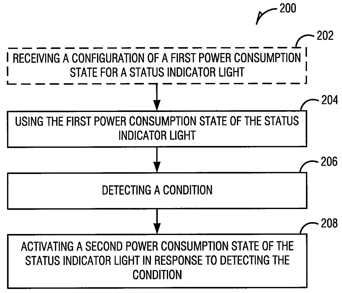
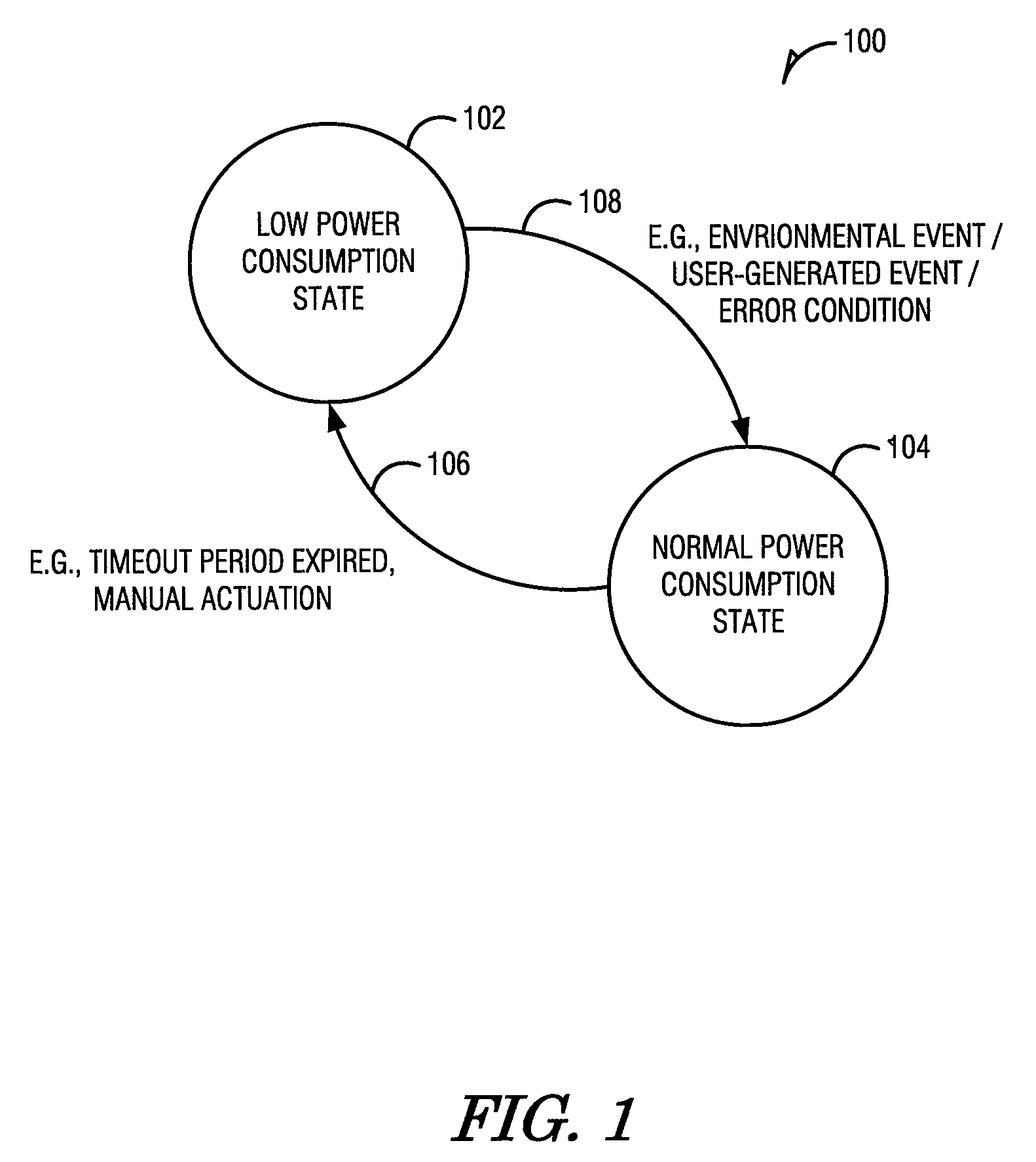
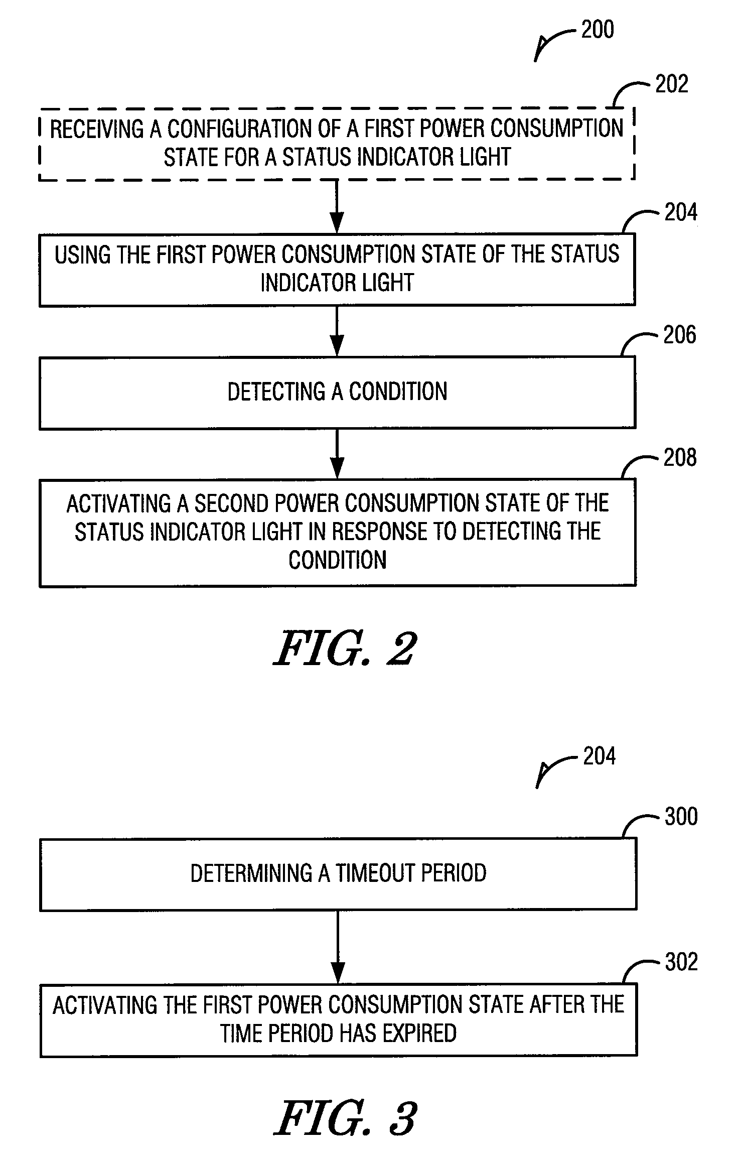
[0037]The example embodiments described herein present methods and apparatus for implementing energy-saving indicator lights. One technique of providing energy-saving indicator lights includes configuring the indicator lights to be active using a configuration mode. For example, one configuration mode uses a single indicator light to indicate a general system status, thereby saving power by not illuminating additional indicator lights. In such a mode, when a condition occurs, such as an error, additional indicator lights may be illuminated to assist in troubleshooting and maintenance.

[0038]Another mode may use a blinking pattern to conserve power. For example, during normal operation, a link carrier detect indicator light may blink at 1 Hz (one short duty cycle pulse every second). The blink frequency may be configurable. In addition, the blink frequency may be constrained to avoid inducing medical conditions, such as photosensitive seizures in people with certain epileptic conditio...


PUM


Abstract

The embodiments described herein present methods and apparatus for an energy-saving status indicator. A method includes receiving a configuration of a first power consumption state for a status indicator light in a network device. The method then activates the first power consumption state using the configuration. After detecting a condition, the method activates a second power consumption state for the status indicator light. The transition from the first power state to the second power state may be from a low power state to a normal operating state or from a normal operating state to a low power state in various embodiments. Other embodiments are described.

Description

FIELD[0001]The present disclosure relates generally to power control in network appliances. In an example embodiment, the disclosure relates to an energy-saving status indicator.BACKGROUND[0002]High density routers and similar equipment often have dozens or hundreds of cables used to carry network traffic to other network devices. In some cases, each of the link cables is associated with one or more link status indicator lights. Such lights may be presented on the front face of the equipment, for example. The link status indicator lights may provide information regarding the link condition, such as “in service,”“active,”“busy,”“error,” or link speed, by using blink patterns or status indicator light color. Such link status indicator lights may be used, for example, by technicians when installing or troubleshooting, to determine the link status and ensure correct operation.BRIEF DESCRIPTION OF DRAWINGS[0003]The present disclosure is illustrated by way of example and not limitation in...

Claims


Application Information

Patent Timeline
Patent Type & Authority Applications(United States)
IPC IPC(8): G08B21/00
CPCY02D50/40H04L12/12Y02D30/50
Inventor BYERS, CHARLES CALVINKLECKA, RUDOLPH BENEDICTMERCADO, FREDDY ALEJANDRO
Owner CISCO TECH INC
Why Eureka
Try Eureka