System and method for three-dimensional alignment of objects using machine vision

a machine vision and object technology, applied in the field of machine vision systems and methods, can solve the problems of limiting the effectiveness of algorithms and tools based on the acquisition of two-dimensional images, affecting the accuracy of machine vision, and the alignment of objects that were clearly recognized by the system in one orientation may be less-recognizable or unrecognizable to the system, etc., to achieve the effect of enhancing the edge features, and reducing the difficulty of machine vision acquisition

Active Publication Date: 2010-07-01
COGNEX CORP
View PDF14 Cites 176 Cited by
  • Summary
  • Abstract
  • Description
  • Claims
  • Application Information

AI Technical Summary

Problems solved by technology

However, the alignment of many objects is not completely resolvable in only two dimensions due to their geometry and surface coloration / shading.
In many cases the geometrical complexity of the object, and / or the need to accurately align with respect to an element of the object that projects in a third dimension may limit the effectiveness of algorithms and tools that are based on the acquisition of two-dimensional images.
Thus, the alignment of an object that was clearly recognized by the system in one orientation may be less-recognizable or unrecognizable to the system in a slightly different orientation.
A significant amount of useful information about a 3D scene or 3D object is lost when that scene or object is projected onto a 2D image.
The loss of this depth data may make it significantly more difficult to accurately and robustly determine the 3D pose of objects.
However, the process of computing z values consumes additional time when compared with the acquisition of only a two-dimensional image.
Achieving a rapid, robust, and accurate 3D alignment solution using a 3D sensor system is a technically challenging problem.

Method used


Image

  • System and method for three-dimensional alignment of objects using machine vision
  • System and method for three-dimensional alignment of objects using machine vision
  • System and method for three-dimensional alignment of objects using machine vision

Examples


Embodiment Construction

[0027]I. System Setup

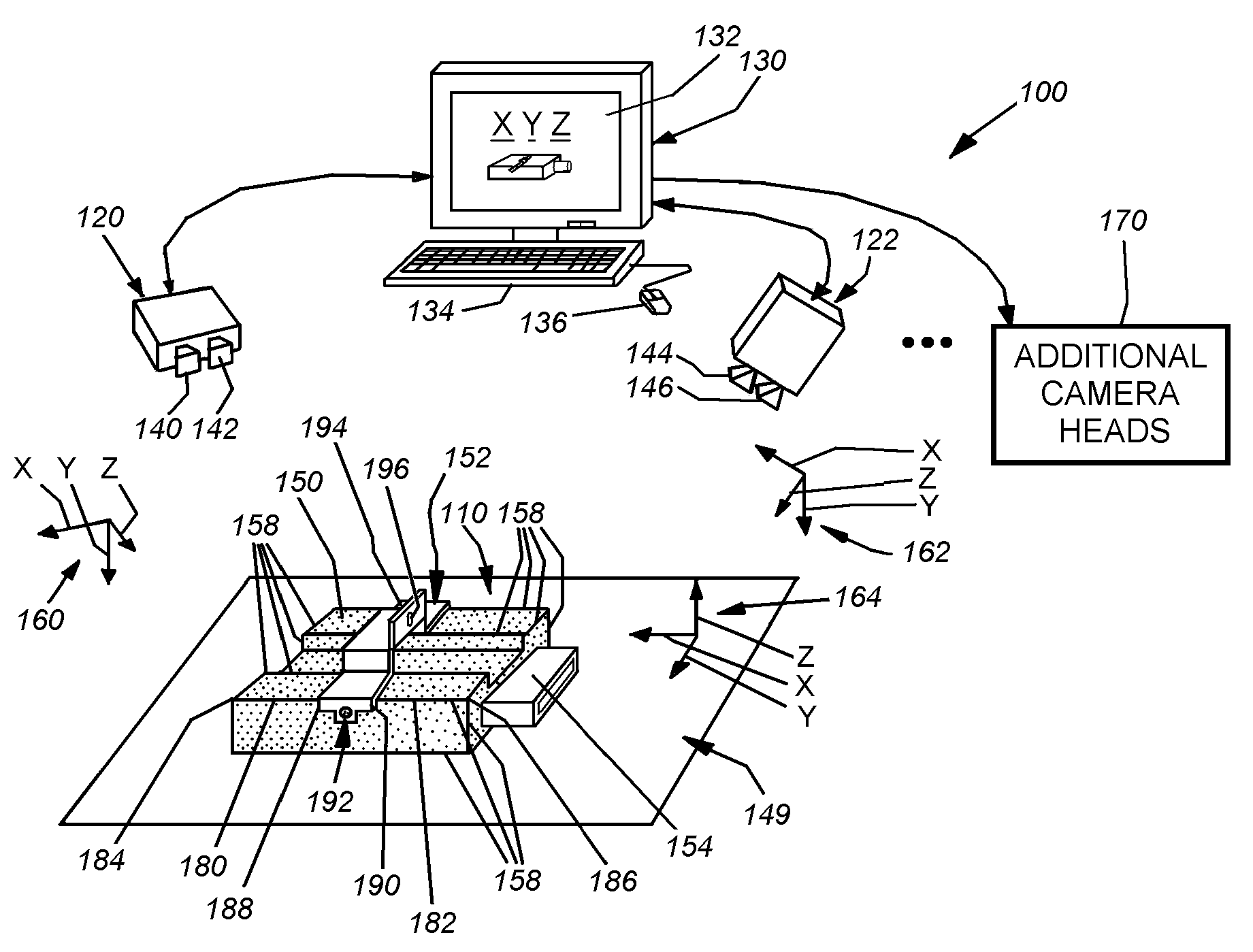
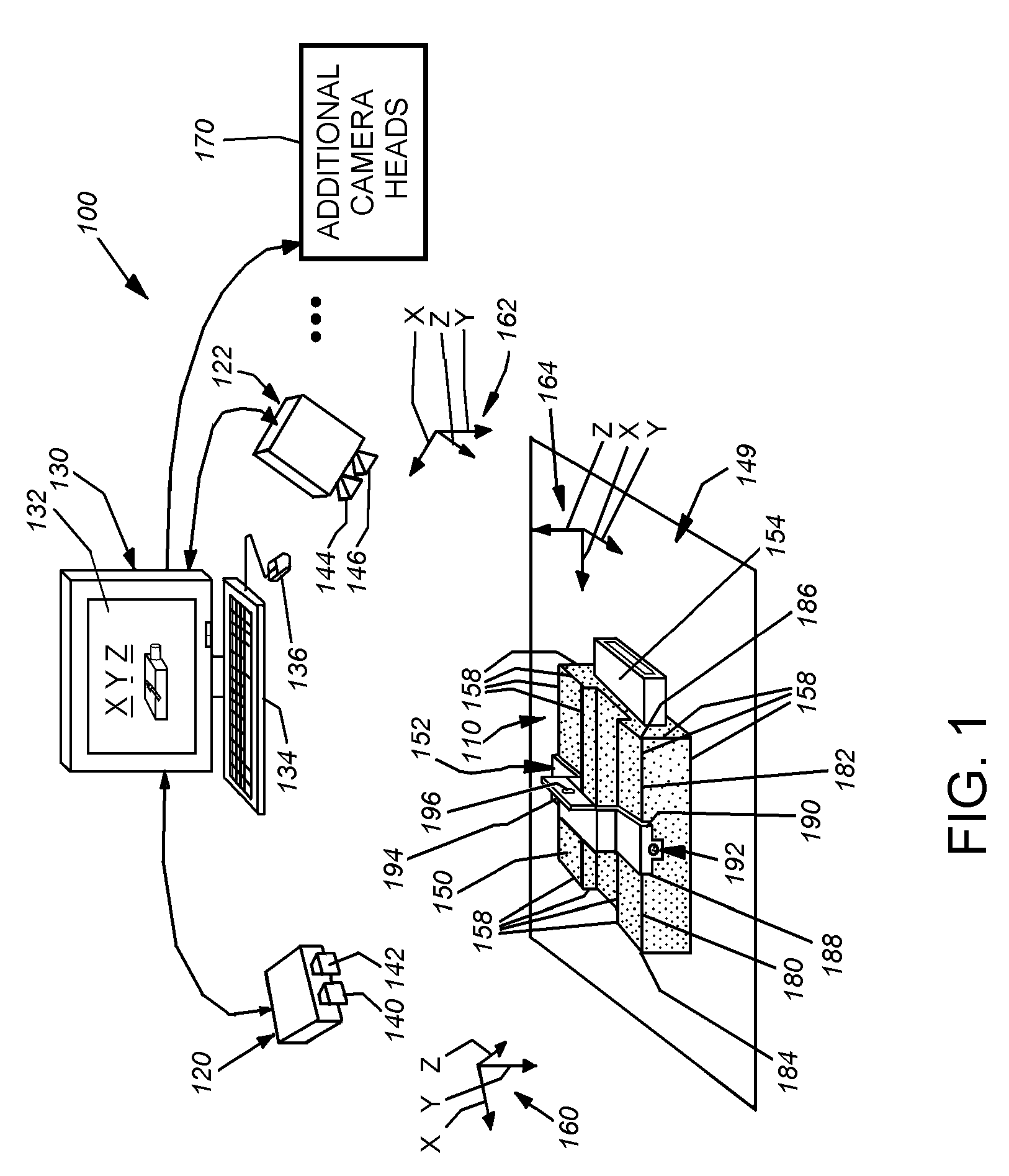
[0028]FIG. 1 depicts a typical arrangement for a system 100 for determining the three-dimensional alignment, or pose, of a viewed object 110 according to an illustrative embodiment of this invention. In this example the system 100 employs a plurality of exemplary three-dimensional stereo camera heads 120 and 122 that are interconnected with an exemplary image processing system 130. In this example, the image processing system is a PC-type computer having a display 132, keyboard 134 and mouse interface 136. The PC includes appropriate video processing components and executes program instructions contained in a computer-readable medium that enable the system and method in accordance with this invention. It should be clear to those of skill in the art, that a PC is only one type of image processing device. In alternate embodiments, the processing components can reside directly within the housings of one or more of the stereo head cameras (or other 3D sensors), and ...


PUM


Abstract

This invention provides a system and method for determining the three-dimensional alignment of a modeledobject or scene. After calibration, a 3D (stereo) sensor system views the object to derive a runtime 3D representation of the scene containing the object. Rectified images from each stereo head are preprocessed to enhance their edge features. A stereo matching process is then performed on at least two (a pair) of the rectified preprocessed images at a time by locating a predetermined feature on a first image and then locating the same feature in the other image. 3D points are computed for each pair of cameras to derive a 3D point cloud. The 3D point cloud is generated by transforming the 3D points of each camera pair into the world 3D space from the world calibration. The amount of 3D data from the point cloud is reduced by extracting higher-level geometric shapes (HLGS), such as line segments. Found HLGS from runtime are corresponded to HLGS on the model to produce candidate 3D poses. A coarse scoring process prunes the number of poses. The remaining candidate poses are then subjected to a further more-refined scoring process. These surviving candidate poses are then verified by, for example, fitting found 3D or 2D points of the candidate poses to a larger set of corresponding three-dimensional or two-dimensional model points, whereby the closest match is the best refined three-dimensional pose.

Description

FIELD OF THE INVENTION[0001]This invention relates to machine vision systems and methods used for alignment of objects with respect to a reference frame; and more particularly to systems and methods for alignment of parts with respect to a three-dimensional reference frame.BACKGROUND OF THE INVENTION[0002]Machine vision has become an essential component in many modern manufacturing processes. One particular use for machine vision is to determine the alignment or pose of a particular component or surface so that the component or surface can be operated on by a tool or robotic manipulator that requires knowledge as to how to orient itself to engage and pick up the component, or perform work on the component or surface. For example, a parts picker that lifts bolts from a bin requires knowledge as to the location of the head of the bolt and the direction in which it is oriented to properly grasp the bolt and direct it to a given target bolt hole in a device under construction.[0003]The ...

Claims


Application Information

Patent Timeline
Patent Type & Authority Applications(United States)
IPC IPC(8): G06K9/00
CPCG06K9/00214G06K9/6211G06V20/653G06V10/757
Inventor MARRION, CYRIL C.FOSTER, NIGEL J.LIU, LIFENGLI, DAVID Y.SHIVARAM, GURUPRASADWALLACK, AARON S.YE, XIANGYUN
Owner COGNEX CORP
Why Eureka
Try Eureka