Camera module array for obtaining compound images

a camera module array and compound image technology, applied in the field of optical imaging, can solve the problems of troublesome assembly complex structure of camera module arrays,

Inactive Publication Date: 2010-07-01
HON HAI PRECISION IND CO LTD
View PDF10 Cites 153 Cited by
  • Summary
  • Abstract
  • Description
  • Claims
  • Application Information

AI Technical Summary

Problems solved by technology

However, the camera module array generally has a complex structure, and it can be troublesome to assemble the camera module array.

Method used


Image

  • Camera module array for obtaining compound images
  • Camera module array for obtaining compound images
  • Camera module array for obtaining compound images

Examples


Embodiment Construction

[0011]Various embodiments will now be described in detail below with reference to the drawings.

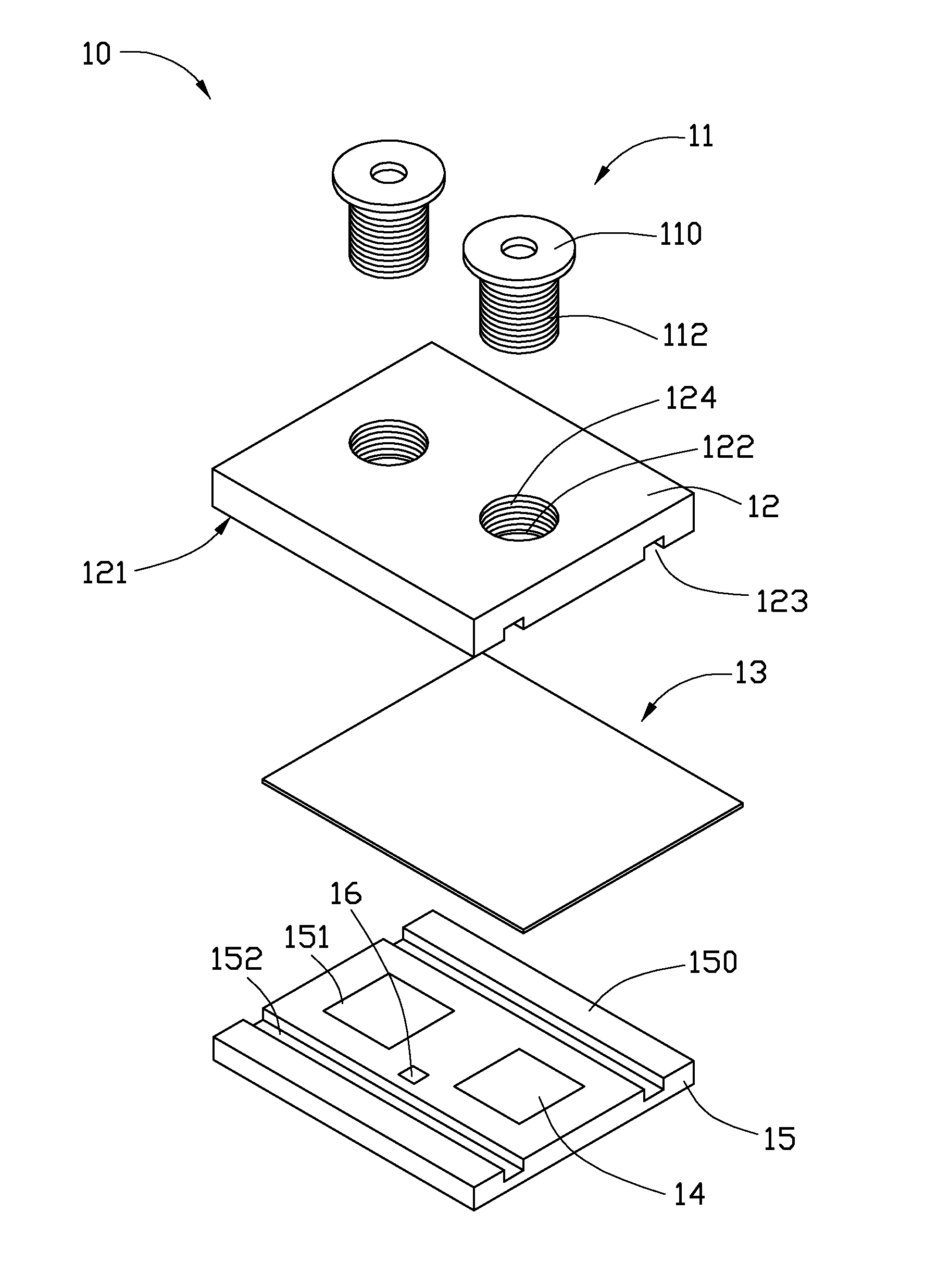
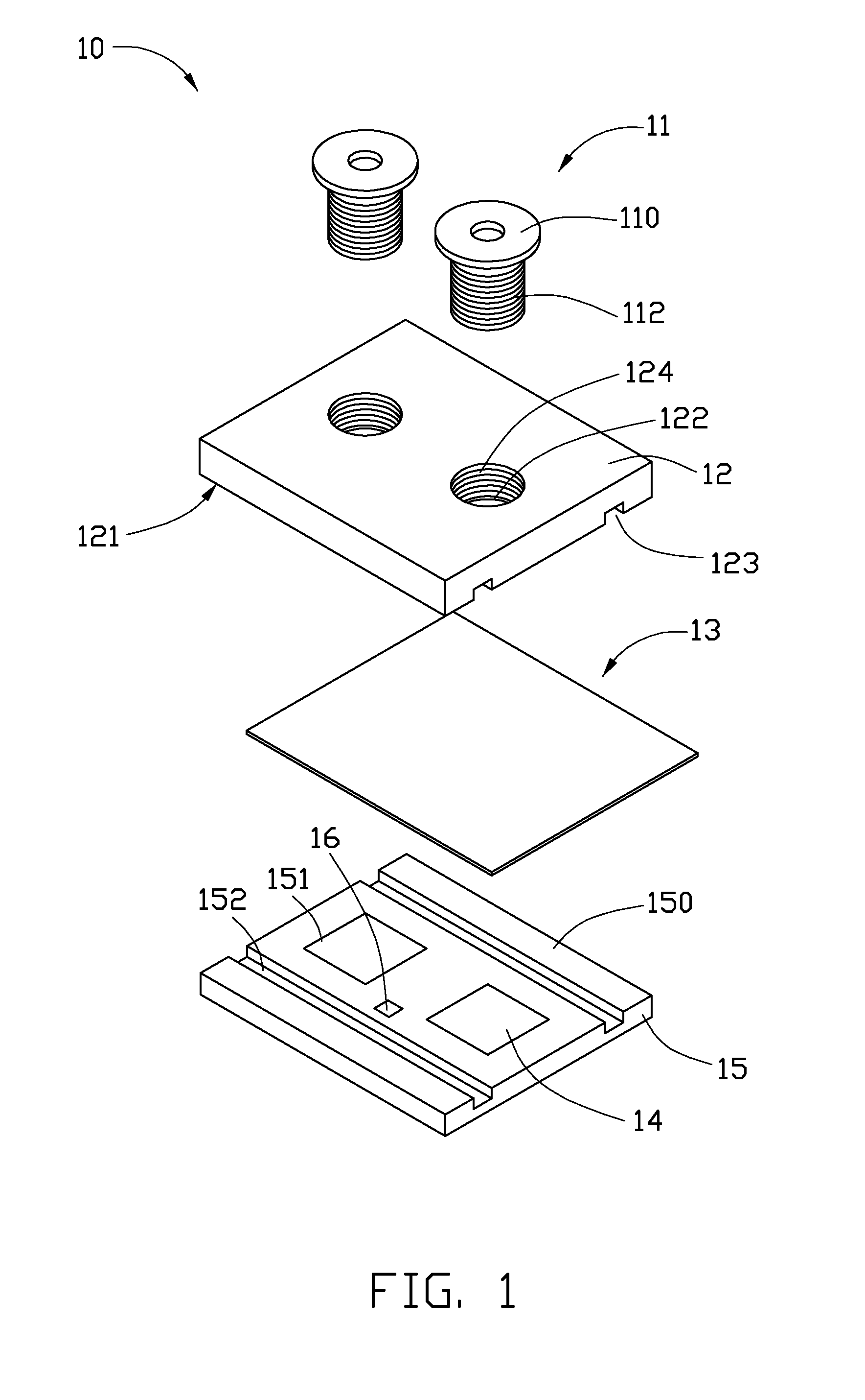
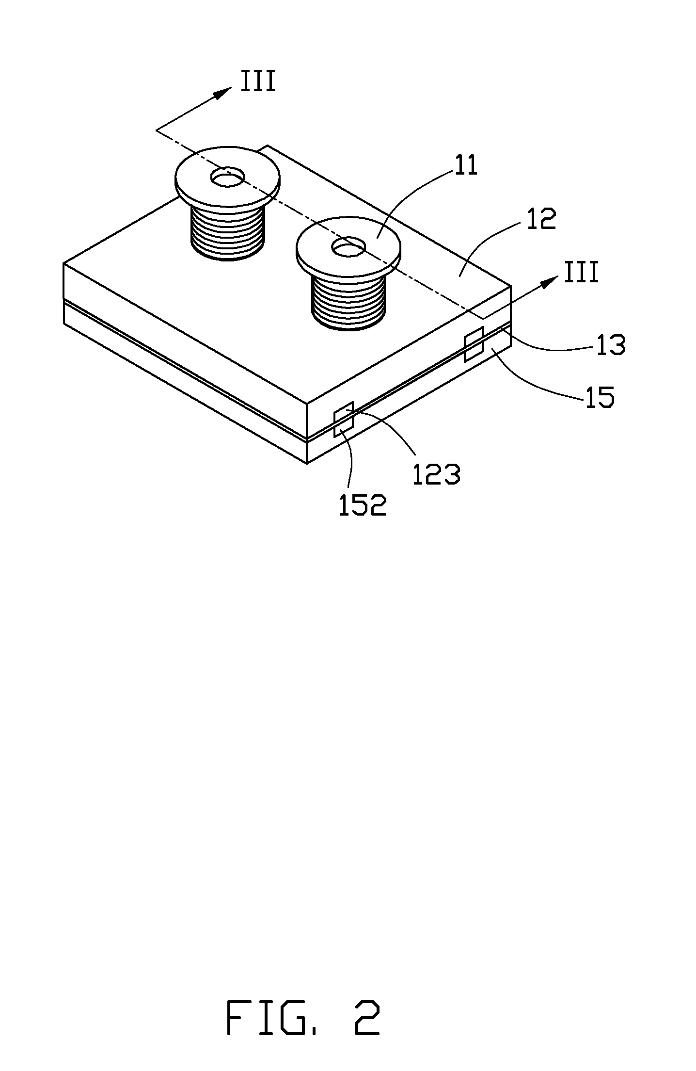
[0012]Referring to FIGS. 1-3, a camera module array 10 according to a first embodiment of the present disclosure is shown. The camera module array 10 includes two lens modules 11, a first holder 12, an optical element 13, two image sensors 14, a second holder 15, and an image processor 16.

[0013]Each lens module 11 includes a barrel 110, and a plurality of lenses 111 received in the barrel 110. The barrel 110 includes an external screw thread 112 formed on an outer surface thereof. The two lens modules 11 have an identical focal length. Alternatively, the two lens modules 11 can have different focal lengths.

[0014]The first holder 12 includes a first surface 121 facing toward the second holder 15, two through holes 122, and two glue trenches 123 defined in the first surface 121. Each through hole 122 has an internal screw thread 124 formed on inner wall thereof. The two glue trenches 123 are...


PUM


Abstract

An exemplary camera module array includes lens modules, a first holder, image sensors, a second holder, an optical element, and an image processor. The lens modules are threadedly coupled to the first holder. The image sensors are in optical alignment with the lens modules in one-to-one relation. The image sensors are received in the second holder. The optical element is sandwiched between the first holder and the second holder. The image processor is electrically connected with the image sensors. The image processor is configured for processing image signals from the image sensors and thereby obtaining a compound image.

Description

BACKGROUND[0001]1. Technical Field[0002]The present disclosure relates to optical imaging, and particularly to a camera module array for obtaining compound images (e.g., stereo images).[0003]2. Description of Related Art[0004]Camera modules are in widespread use nowadays. In order to provide multifunctional features such as the ability to capture stereo (three-dimensional) images, etc, a camera module array including a plurality of camera modules is used. However, the camera module array generally has a complex structure, and it can be troublesome to assemble the camera module array.[0005]Therefore, a new camera module array is desired to overcome the above-mentioned problems.BRIEF DESCRIPTION OF THE DRAWINGS[0006]Many aspects of the embodiments can be better understood with reference to the following drawings. The components in the drawings are not necessarily drawn to scale, the emphasis instead being placed upon clearly illustrating the principles of the present embodiments. More...

Claims


Application Information

Patent Timeline
Patent Type & Authority Applications(United States)
IPC IPC(8): G03B35/00
CPCG03B35/00
Inventor CHANG, JEN-TSORNG
Owner HON HAI PRECISION IND CO LTD
Why Eureka
Try Eureka