Centrifugal compressor

Inactive Publication Date: 2010-07-01
MITSUBISHI HEAVY IND LTD
View PDF5 Cites 9 Cited by
  • Summary
  • Abstract
  • Description
  • Claims
  • Application Information

AI Technical Summary

Benefits of technology

[0032]According to the centrifugal compressor in the invention, since the flow channels of the diffuser section and the volute section are divided into the hub-side flow channels and the shroud-side flow channels, so that the respective flow channels are used properly de

Problems solved by technology

However, the technology disclosed in Patent Document 1 has a problem such that a significant improvement cannot be expected although the operating range of the centrifugal compressor is somewhat widened by casing treatment as shown in FIG. 18.
The technologies disclosed in Patent Documents 2, 3, 4 and 5 have a problem of being economically ineffici

Method used


Image

  • Centrifugal compressor
  • Centrifugal compressor
  • Centrifugal compressor

Examples


first embodiment

[0070]Referring now to the drawings, a first embodiment of the invention will be described.

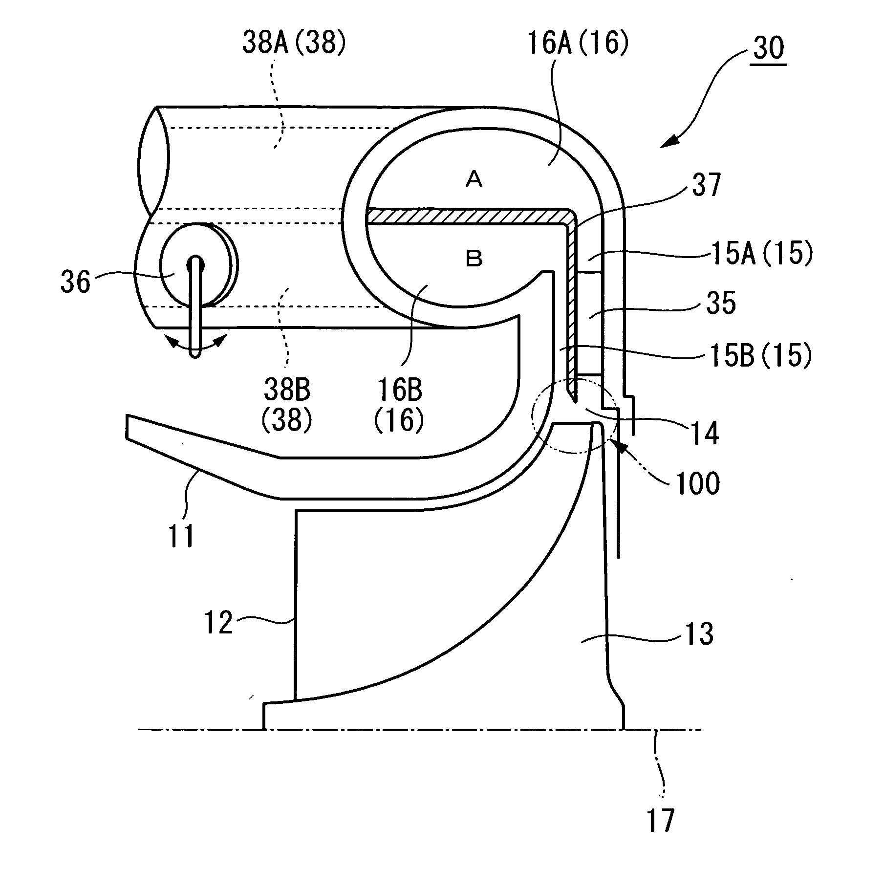
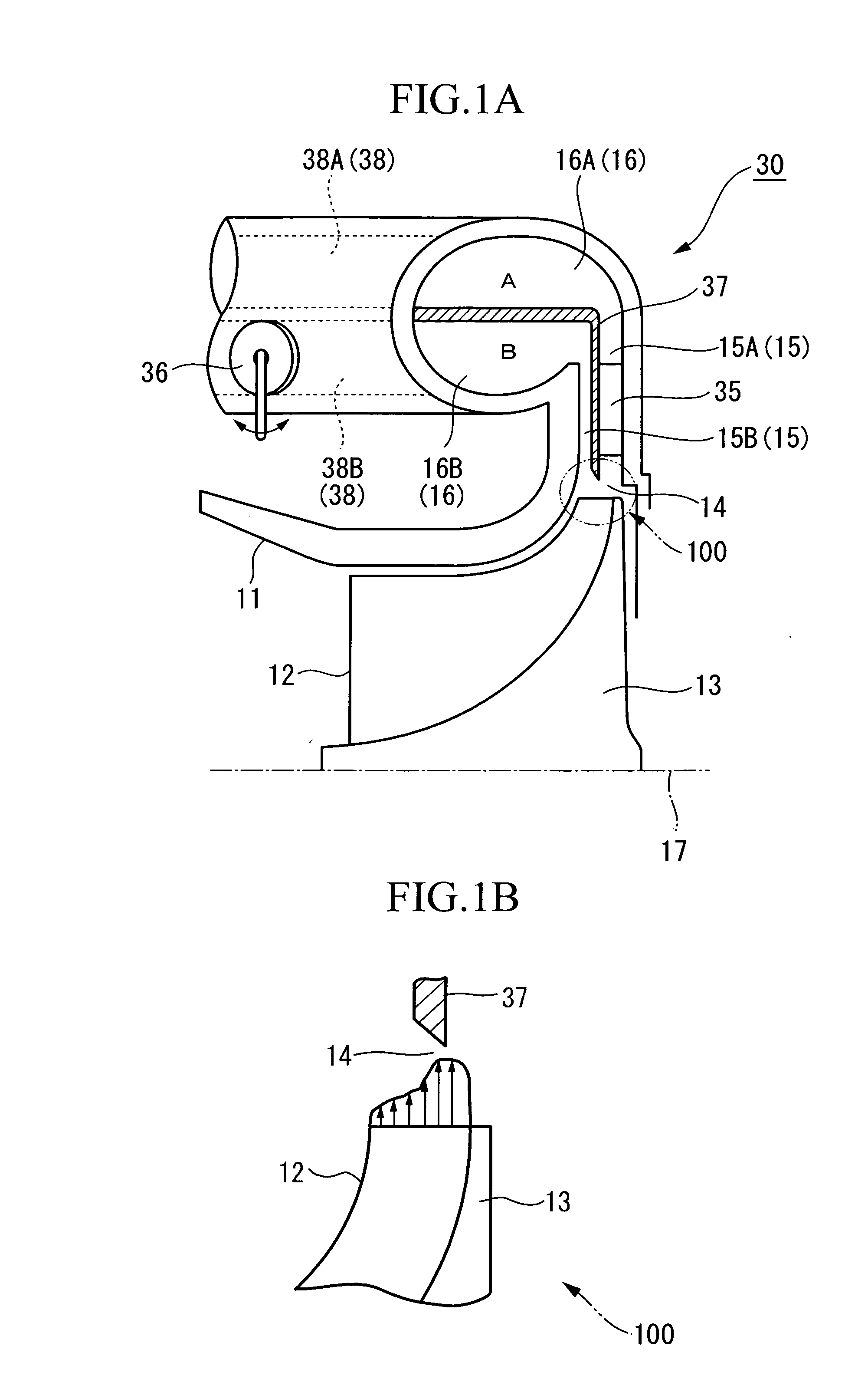
[0071]FIG. 1A shows a vertical cross-sectional view of a centrifugal compressor 30 according to the first embodiment. FIG. 1B shows a flow velocity distribution at the time of discharge from an impeller.

[0072]In FIG. 1A, the centrifugal compressor 30 includes an impeller 13 having a plurality of blades 12 and a casing 11 for housing the impeller 13.

[0073]The impeller 13 is rotated about an axis of rotation 17 by a drive assembly such as a motor or a turbine, not shown. The impeller 13 includes a diffuser section 15 and a volute section 16 on the discharge side of the impeller 13 provided continuously.

[0074]The diffuser section 15 reduces the velocity of air flow discharged from the outer peripheral end of the impeller 13 which rotates in the casing 11 and recovers a static pressure.

[0075]The volute section 16 is connected to the diffuser section 15 on the downstream side and is provided with a...

second embodiment

[0098]Referring now to FIG. 7, a second embodiment of the invention will be described.

[0099]A centrifugal compressor in the second embodiment is different from that in the first embodiment in that the vanes are provided both on the hub-side diffuser section 15A and the shroud-side diffuser section 15B. The centrifugal compressor in the second embodiment will be described mainly on the different point from the first embodiment, while omitting description of the points which are common to the first embodiment.

[0100]As shown in FIG. 7, the hub-side diffuser section 15A and the shroud-side diffuser section 15B are provided with the vanes 35. The vanes 35 are arranged circumferentially at predetermined distances and are fixed to the casing 11.

[0101]The number of vanes 35A installed on the hub-side diffuser section 15A is larger than the number of vanes 35B installed on the shroud-side diffuser section 15B. Accordingly, the cross-sectional area of the flow channel of the hub-side diffuser...

third embodiment

[0110]Referring now to FIG. 10, a third embodiment of the invention will be described.

[0111]A centrifugal compressor in the third embodiment is different from that in the embodiments shown above in that the vane is provided neither on the hub-side diffuser section 15A nor the shroud-side diffuser section 15B. The centrifugal compressor in the third embodiment will be described mainly on the different point from the embodiments shown above, while omitting description of the points which are common to the embodiments shown above.

[0112]As shown in FIG. 10, the hub-side diffuser section 15A and the shroud-side diffuser section 15B are not provided with the vane. The cross-sectional area of the flow channel of the hub-side diffuser section 15A is set to be smaller than the cross-sectional area of the flow channel of the shroud-side diffuser section 15B.

[0113]The flow rate adjusting valve (flow rate adjuster) 36 for adjusting the flow rates in the respective flow channels is provided in t...


PUM


Abstract

A centrifugal compressor having a wide operating range, being economically efficient and high reliability in terms of a stable operation is provided. A centrifugal compressor including a partition wall 37 for dividing a flow channel in the diffuser section 15 and the volute section 16 into a plurality of channels in the direction of circulation of the fluid so as to define a hub-side flow channel A and a shroud-side flow channel B; and a flow rate adjusting valve 36 for lowering the flow rate of the fluid flowing in the shroud-side flow channel B to increase the flow rate in the hub-side flow channel A when the flow rate of the fluid compressed by an impeller 13 is low and not lowering the flow rate of the fluid flowing the shroud-side flow channel B to allow the fluid to flow both in the shroud-side flow channel B and the hub-side flow channel A when the flow rate of the fluid compressed by the impeller 13 is high is employed.

Description

TECHNICAL FIELD[0001]The present invention relates to a centrifugal compressor used for a turbocharger or the like.BACKGROUND ART[0002]In the related art, for example, a centrifugal compressor used for a turbocharger or the like of an internal combustion engine for motor vehicles is known.[0003]FIG. 13 is a front view of a principle portion of a centrifugal compressor in the related art. FIG. 14 is a vertical cross-sectional view of a principal portion of the centrifugal compressor in the related art. A centrifugal compressor 10 in the drawing compresses fluid such as gas or air introduced from the outside of a casing 11 by rotating an impeller 13 provided with a number of blades 12 in the casing 11. The flow of fluid (air flow) formed in this manner is sent to the outside via an impeller exit (hereinafter, referred also to as “diffuser section inlet”) 14 which corresponds to the outer peripheral end of the impeller 13, a diffuser section 15 and a volute section 16. Reference numera...

Claims


Application Information

Patent Timeline
IPC IPC(8): F04D29/46
CPCF04D29/4206F04D29/422F04D29/441F04D29/462F04D29/464F05D2250/52F04D17/08F05D2210/12Y10S415/00Y10S417/00
Inventor IBARAKI, SEIICHITOMITA, ISAOJINNAI, YASUAKISHIRAISHI, TAKASHISUGIMOTO, KOICHI
Owner MITSUBISHI HEAVY IND LTD
Why Eureka
Try Eureka