Method and apparatus for calibrating position and attitude of arm tip of robot

a robot arm and arm tip technology, applied in the field of methods and apparatus for calibrating the position and attitude can solve the problems of inconvenient calibration techniques, low accuracy of calibration, and difficulty in measuring the absolute position of the arm tip of the robot, etc., and achieve the effect of higher accuracy

Active Publication Date: 2010-07-01
DENSO WAVE INC
View PDF17 Cites 37 Cited by
  • Summary
  • Abstract
  • Description
  • Claims
  • Application Information

AI Technical Summary

Benefits of technology

[0032]The present invention has been made in consideration with the forgoing difficulties, and an object of the present invention is to calibrate the position and attitu

Problems solved by technology

In consequence, the calculation for obtaining the robot physical parameter should will include the errors given by the foregoing two types of additional information i) and ii), resulting in that accuracy of the calibration will decrease due to the additional inclusion of the errors.
Additionally, the calibration technique taught by the foregoing publication is faced with an inconvenience resulting from estimatio

Method used


Image

  • Method and apparatus for calibrating position and attitude of arm tip of robot
  • Method and apparatus for calibrating position and attitude of arm tip of robot
  • Method and apparatus for calibrating position and attitude of arm tip of robot

Examples


first embodiment

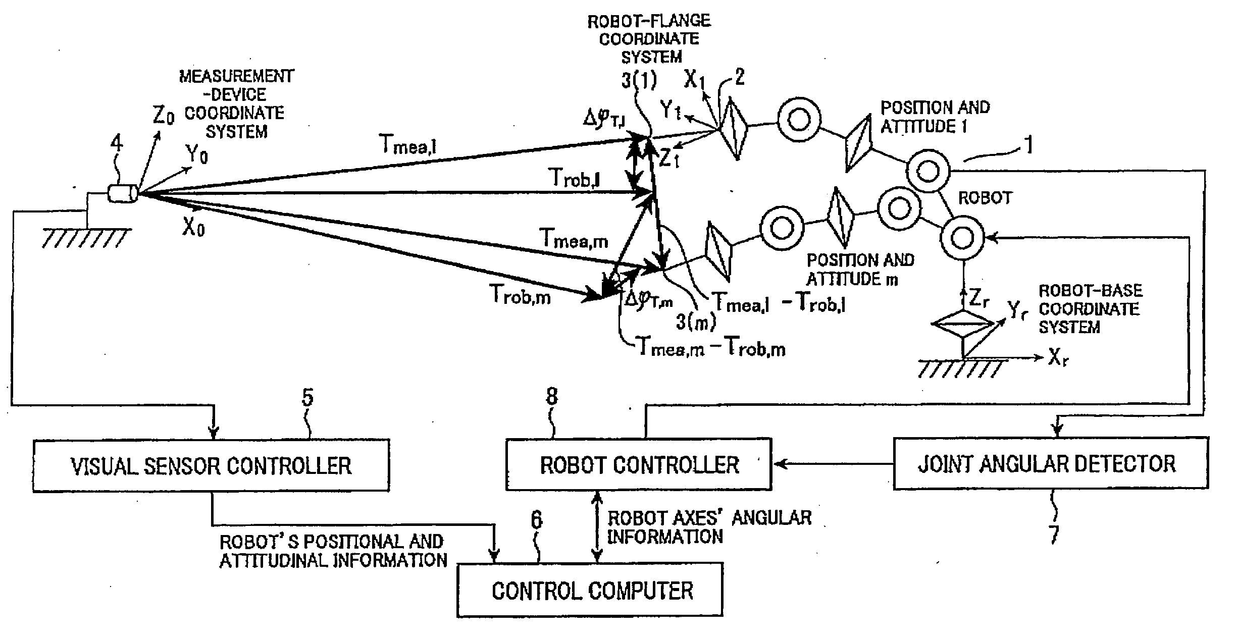
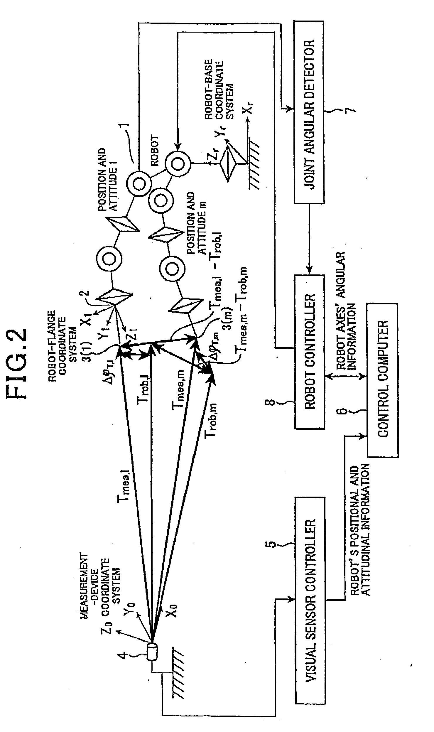
[0043]Referring to FIGS. 2 and 3, a first embodiment of the calibration apparatus according to the present invention will now be described.

[0044]The configuration of a robot system shown in FIG. 2 is the same as that shown in FIG. 1 except for a technique for calibration which is performed by the control computer 6. Hence, the same components in FIG. 2 are given the same reference numerals as those shown in FIG. 1 for a simplified description.

[0045]Practically, in the configuration in FIG. 1, the arm tip of the robot 1, which is the tip of the tool 3, is calibrated for its one position and attitude by calculating an error between a measured result of the measurement device 4 and a control result of the control computer 6. By contrast, in the present embodiment, the arm tip of the robot 1 is calibrated in tow control modes in which the arm tip is controlled at a position and attitude (position / attitude) “1” and a position and attitude (position / attitude) “m”. In each control mode, th...

second embodiment

[0068]Referring to FIG. 4, a second embodiment of the calibration apparatus according to the present invention will now be described.

[0069]The second embodiment and subsequent embodiment adopt the same hardware configuration of the robot system as that described in FIG. 2. Hence, the components which are the same as those in the first embodiment are given the same reference numerals for a simplified description.

[0070]While the reference position and attitude m in the first embodiment is given only one point, the reference position and attitude m is given a plurality of points (=1 to l) for the calibration in the second embodiment. In this case, as for the error matrix Δq, the formula (12) is replaced by a formula (21), which is as follows:

Δq=([Jq,1(θ,q)-Jq,m1(θ,q)⋮Jq,n(θ,q)-Jq,m1(θ,q)Jq,1(θ,q)-Jq,m2(θ,q)⋮Jq,n(θ,q)-Jq,m2(θ,q)Jq,1(θ,q)-Jq,m2(θ,q)⋮Jq,n(θ,q)-Jq,m1(θ,q)]t[Jq,1(θ,q)-Jq,m1(θ,q)⋮Jq,n(θ,q)-Jq,m1(θ,q)Jq,1(θ,q)-Jq,m2(θ,q)⋮Jq,n(θ,q)-Jq,m2(θ,q)Jq,1(θ,q)-Jq,m2(θ,q)⋮Jq,n(θ,q)-Jq,m...

third embodiment

[0074]Referring to FIG. 5, a third embodiment of the present invention will now be described.

[0075]The calibration apparatus according to the third embodiment improvise that according to the first embodiment in selecting the positions and attitudes in the arm's movable space.

[0076]In this respect, the first embodiment has been described on condition that, at step S2 in FIG. 3, the positions and attitudes for calibration are selected properly, with almost no bias of selected position within the arm's movable space. This means that the stimulated inverse matrix of a Jacobian determinant can be obtained reliably.

[0077]However, although it is rare, it may happen that the positions and attitudes are selected from only a specific part of the movable space or are erroneously selected partly or entirely from the same positions. In such cases, the stimulated inverse matrix of a Jacobian determinant may not be obtained. Such an undesired situation is covered by the third embodiment.

[0078]If t...


PUM


Abstract

A calibrating technique is provided for the position/attitude or only the position of an arm tip of a robot, such as an articulated type of robot. At plural positions, respective n pieces of errors (Δφn, wherein n is a positive integer larger than a value obtained by dividing the number of unknown parameters by 6 or 3) are calculated. Each error is a difference between a position of the arm tip measured and a position commanded by control. An inter-error difference (Δεy (1≦y≦n−1)) between a reference error (Δφm (1≦m≦n)) arbitrarily selected from the n-piece errors (Δφn) and other errors (Δφx (x≦n, except for m)) other than the reference error (Δφm) is calculated. A parameter, which is a basis for calculating the inter-error differences (Δεy), is made to converge until a sum of absolute values of the inter-error differences (Δεy) becomes within a given threshold (ε0 0>0)).

Description

CROSS-REFERENCE TO RELATED APPLICATION[0001]This application is based on and claims the benefit of priority from earlier Japanese Patent Application No. 2008-322342 filed Dec. 18, 2008, the description of which is incorporated herein by reference.BACKGROUND OF THE INVENTION[0002]1. Technical Field of the Invention[0003]The present invention relates to a method and an apparatus for calibrating the position and attitude of the tip of an arm of a robot, such as an articulated type of robot preferably for use on factory floors.[0004]2. Related Art[0005]Industrial robots equipped with an articulated type of arm (called a manipulator) are now used in various kinds of sites. In such a robot, for reasons which are attributable to errors of motions of mechanical components and other factors, controlling the position of the tip of an arm requires calibration to make an actual position of the arm tip accord with a commanded positional value.[0006]For example, one calibration technique is discl...

Claims


Application Information

Patent Timeline
IPC IPC(8): B25J9/00
CPCB25J9/1692G05B2219/39026G05B2219/40527G05B2219/40557
Inventor KAGAWA, NAOYASATO, TETSUYA
Owner DENSO WAVE INC
Why Eureka
Try Eureka