
Maple spout with interior chamber and maple syrup production system using same

a technology of maple syrup and spout, which is applied in the direction of mechanical equipment, functional valve types, seeds and root treatment, etc., can solve the problems of reducing sap yield, reducing vacuum transfer to the taphole, and reducing sap movement, so as to reduce vacuum transfer, reduce sap yield, and reduce movement

Inactive Publication Date: 2010-07-08
UNIVERSITY OF VERMONT
View PDF22 Cites 14 Cited by
  • Summary
  • Abstract
  • Description
  • Claims
  • Application Information

AI Technical Summary

Benefits of technology

[0009]Current maple industry practice utilizes a line system to collect sap from the tree and deliver it to the evaporator of a maple syrup production system. The sap and gases from the tree move downward in the system from the taphole, through the maple syrup spout, down the drop lines and lateral lines and toward the larger mainline due to gravity and the pull of the vacuum in the lines. The gases move faster in the lines, creating turbulence and resulting in reduced sap movement. In some cases (and particularly in cases where 5 / 16″ ID lines or smaller ID lines are used), portions of the drop lines and / or lateral lines are almost fully occupied by sap, resulting in reduced vacuum transfer to the taphole, which reduces sap yield.
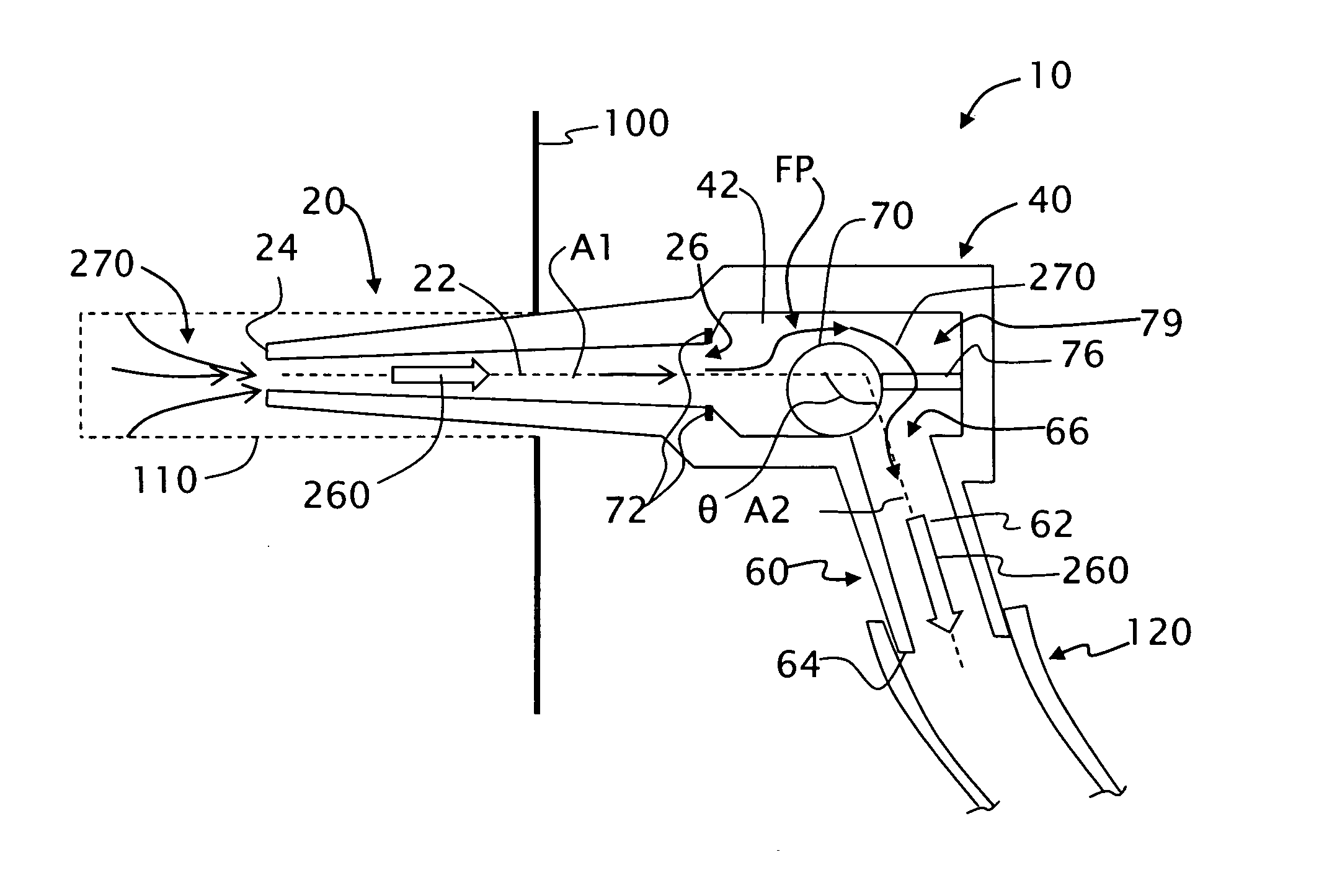
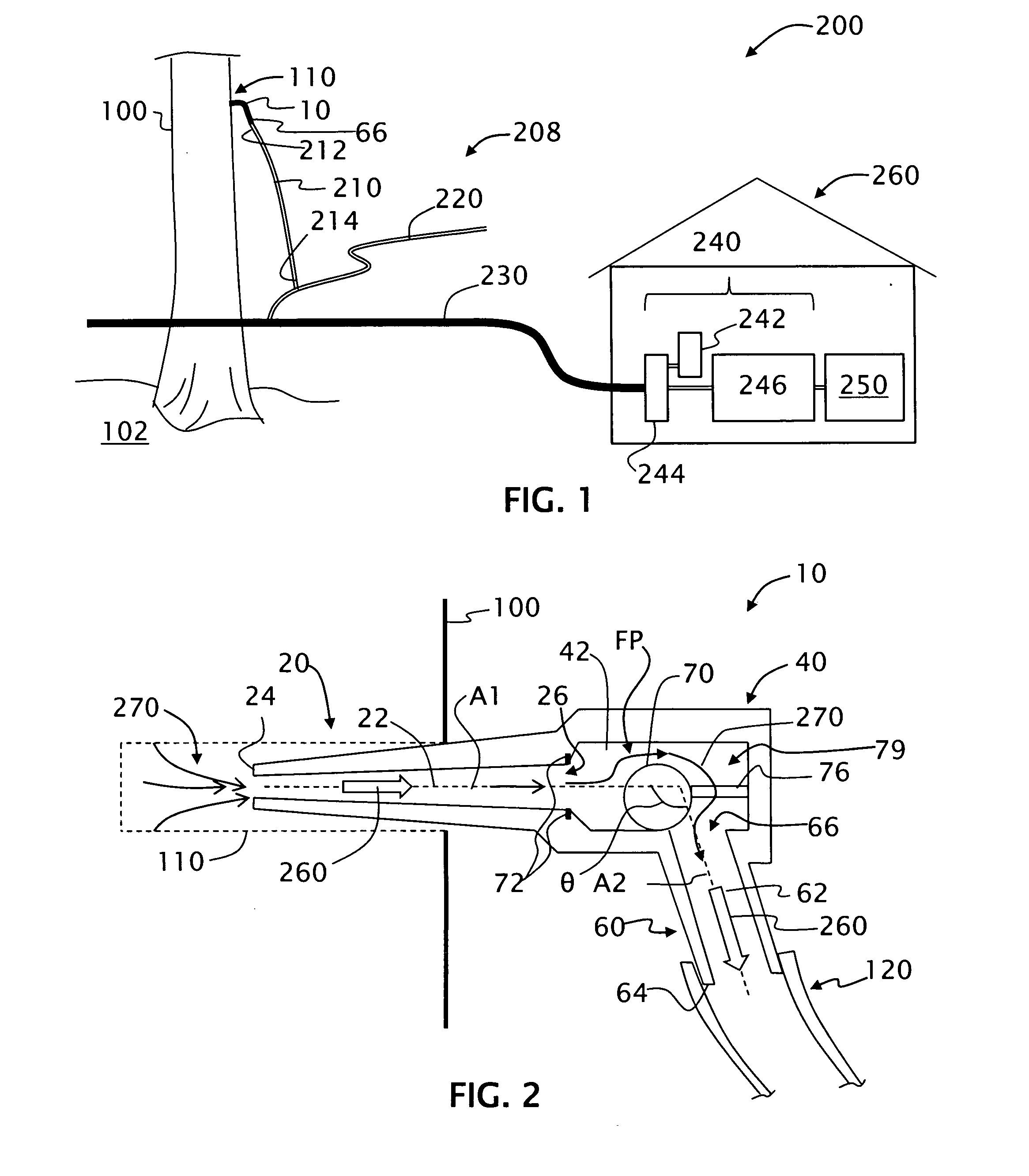
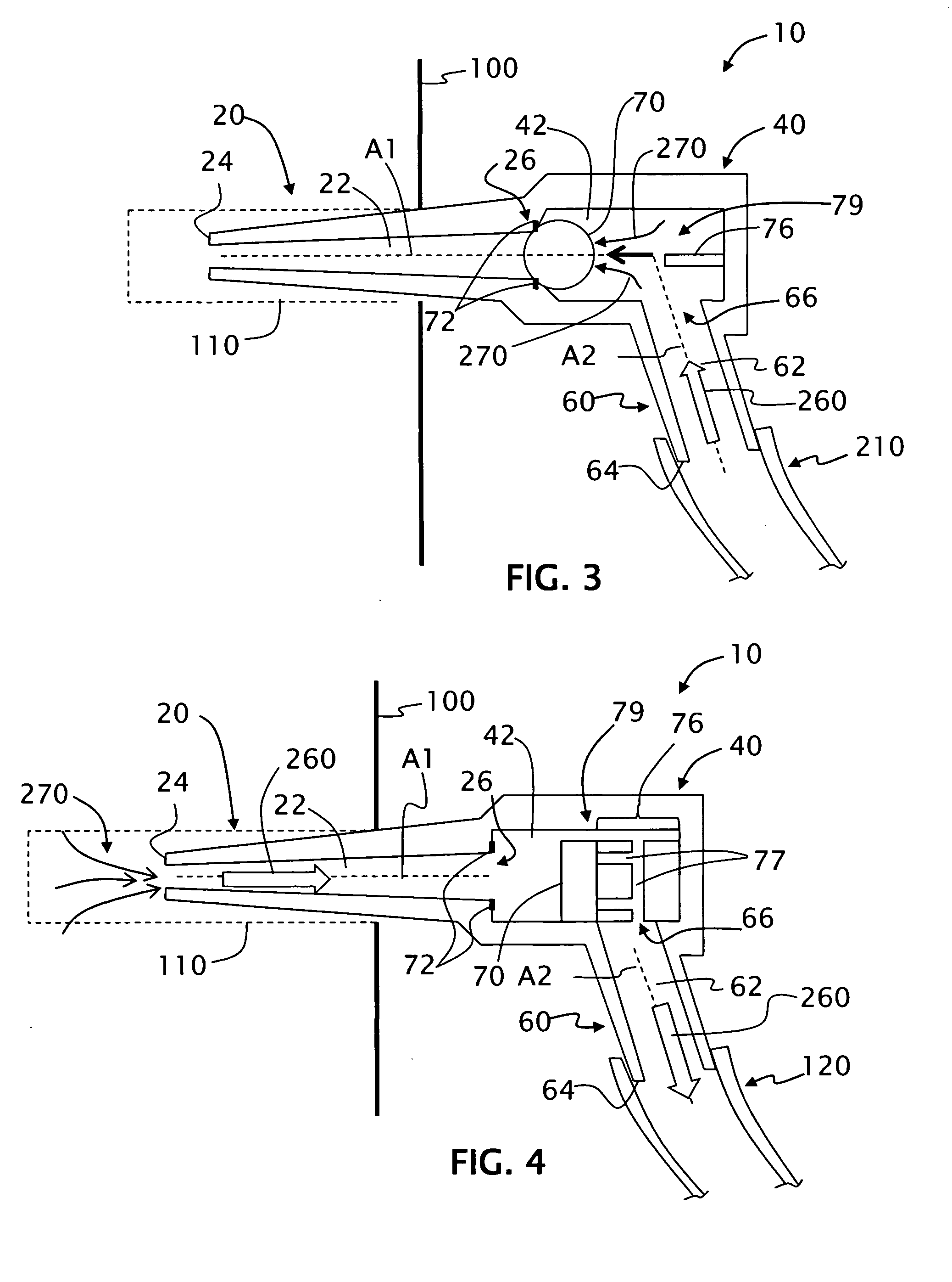
[0010]Accordingly, an aspect of the invention is a spout that includes a main body section having an interior chamber that serves as a reservoir where vacuum can accumulate and where sap can also accumulate during its flow from a nose section and through the main body section to the drop line. The interior chamber facilitates reduced liquid-liquid contact between the tubing system and taphole as compared to prior art maple syrup spouts. This serves to restrict microbial movement from the tubing to the taphole and results in a cleaner taphole and higher sap yield as part of a maple syrup production system that utilizes a line system under vacuum to convey sap from the maple tree.

Problems solved by technology

The gases move faster in the lines, creating turbulence and resulting in reduced sap movement.
In some cases (and particularly in cases where 5 / 16″ ID lines or smaller ID lines are used), portions of the drop lines and / or lateral lines are almost fully occupied by sap, resulting in reduced vacuum transfer to the taphole, which reduces sap yield.

Method used


Image

  • Maple spout with interior chamber and maple syrup production system using same
  • Maple spout with interior chamber and maple syrup production system using same
  • Maple spout with interior chamber and maple syrup production system using same

Examples


Embodiment Construction

[0026]In the description below, the term “fluidly connected” generally includes techniques known in the art of maple syrup production to connect fluid-carrying parts of the production system so that fluid can flow between or through the parts. An exemplary fluid connection technique is a “press fit,” where the end of one part (e.g., a drop line 210, described below) is slid over and pressed onto the end of another part (e.g., a fitting 330 with ridges 332, as described below) to provide a snug fit that is water-tight and vacuum tight. Other fluid connection techniques that are available employ threaded parts or snap-fit parts. However, the present invention is described below using the “press fit” connection technique because it is presently the most widely accepted connection technique in the maple syrup industry.

[0027]Also, while the present invention works well with 5 / 16″ inside diameter (ID) lines (i.e., drop line, lateral lines, etc.), it also works with larger-diameter lines a...


PUM


Abstract

A maple syrup production spout with an interior chamber is disclosed. The spout is designed for use with vacuum-based maple syrup production systems. The interior chamber serves as a reservoir that allows the vacuum to accumulate, thereby facilitating the flow of sap from the tap hole, through the spout and into the dropline. The interior chamber also facilitates reduced liquid-liquid contact between the tubing system and the taphole, which improves the cleanliness of the tap hole and increases sap yield. Methods of using the spout in maple syrup production system are also disclosed.

Description

CROSS-REFERENCE TO RELATED APPLICATIONS[0001]The present application is a continuation-in-part application of U.S. patent application Ser. No. 12 / 286,032, entitled “Maple syrup production spout with backflow check valve,” and filed on Sep. 26, 2008, which application is incorporated by reference herein.[0002]The present application is also related to U.S. patent application Ser. No. ______, entitled “Maple syrup line system with increased diameter lines and fittings,” filed on the same day as the present application, and which application is incorporated by reference herein.FIELD OF THE INVENTION[0003]The present invention relates generally to maple syrup production, and in particular relates to a maple syrup spout with an internal reservoir and a maple syrup production system that uses the maple syrup spout.BACKGROUND ART[0004]Maple syrup production involves drilling holes into (i.e., “tapping”) maple trees, collecting the sap that exudes from the wound, and then reducing or “sugar...

Claims


Application Information

Patent Timeline
IPC IPC(8): A01G23/14A01G1/00
CPCA01G23/14F16K15/04
Inventor PERKINS, TIMOTHY D.
Owner UNIVERSITY OF VERMONT
Learn More