Rotary actuator and manufacturing method of the same

a technology of rotary actuators and manufacturing methods, which is applied in the direction of manufacturing tools, mechanical equipment, and gearing, can solve problems such as affecting the shift position sensor, and achieve the effect of improving the sensing accuracy of the shift position sensor

Inactive Publication Date: 2010-07-08
DENSO CORP
View PDF0 Cites 19 Cited by
  • Summary
  • Abstract
  • Description
  • Claims
  • Application Information

AI Technical Summary

Benefits of technology

[0007]It is an object of the present invention to provide a rotar

Problems solved by technology

There is a concern that inclination of a drive shaft of the shift range switching device conne

Method used


Image

  • Rotary actuator and manufacturing method of the same
  • Rotary actuator and manufacturing method of the same
  • Rotary actuator and manufacturing method of the same

Examples


embodiment

(Embodiment)

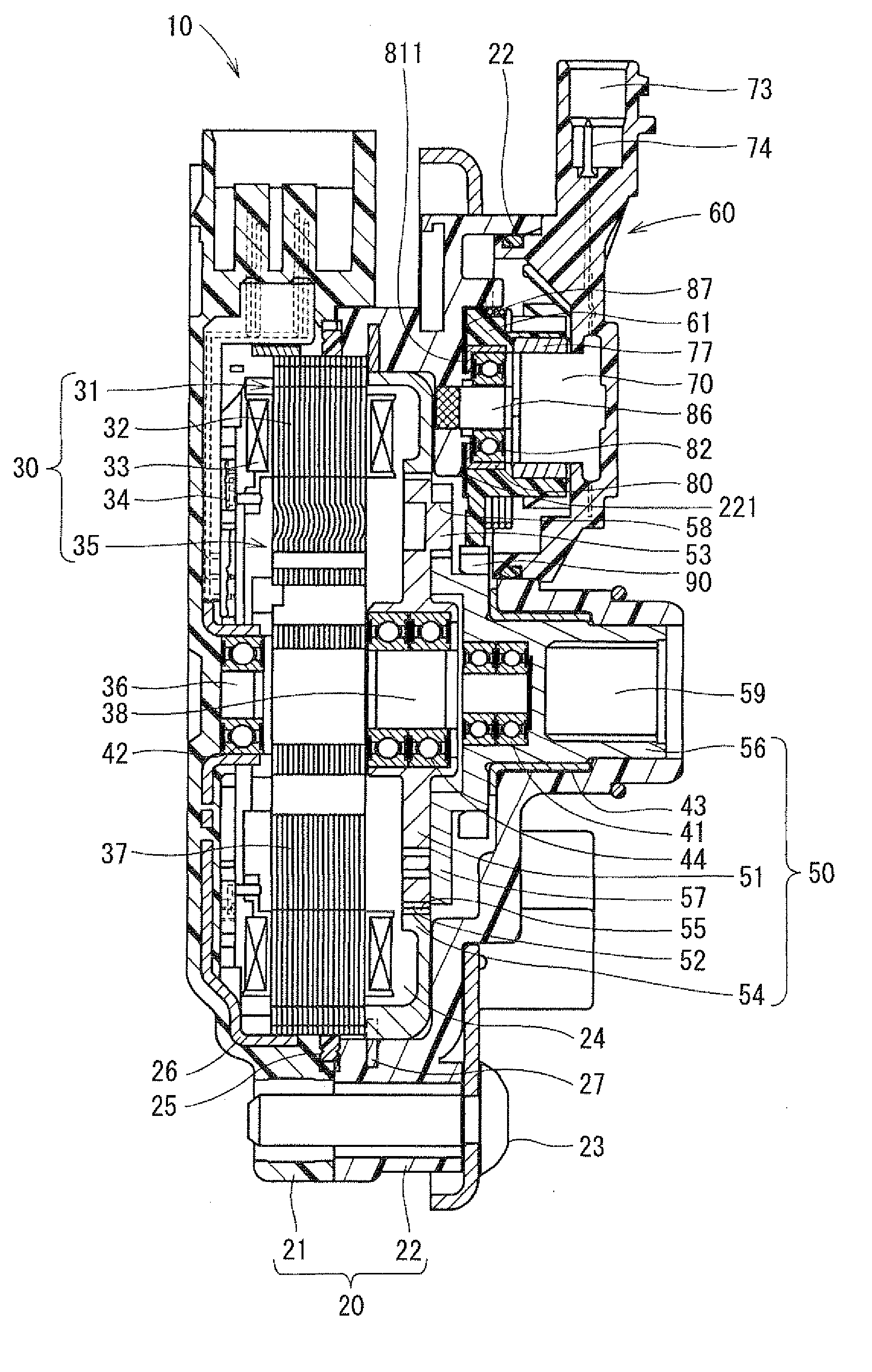
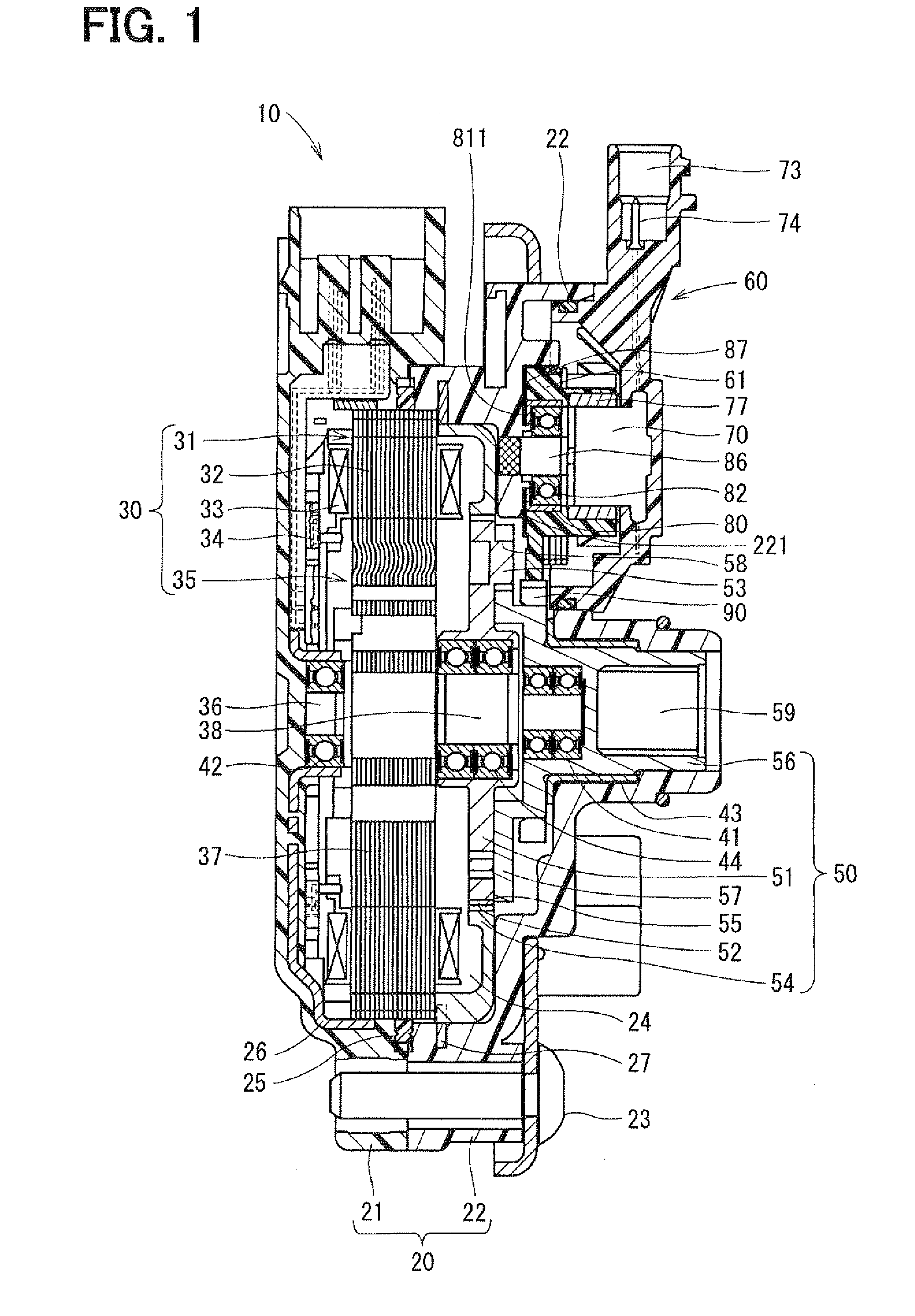
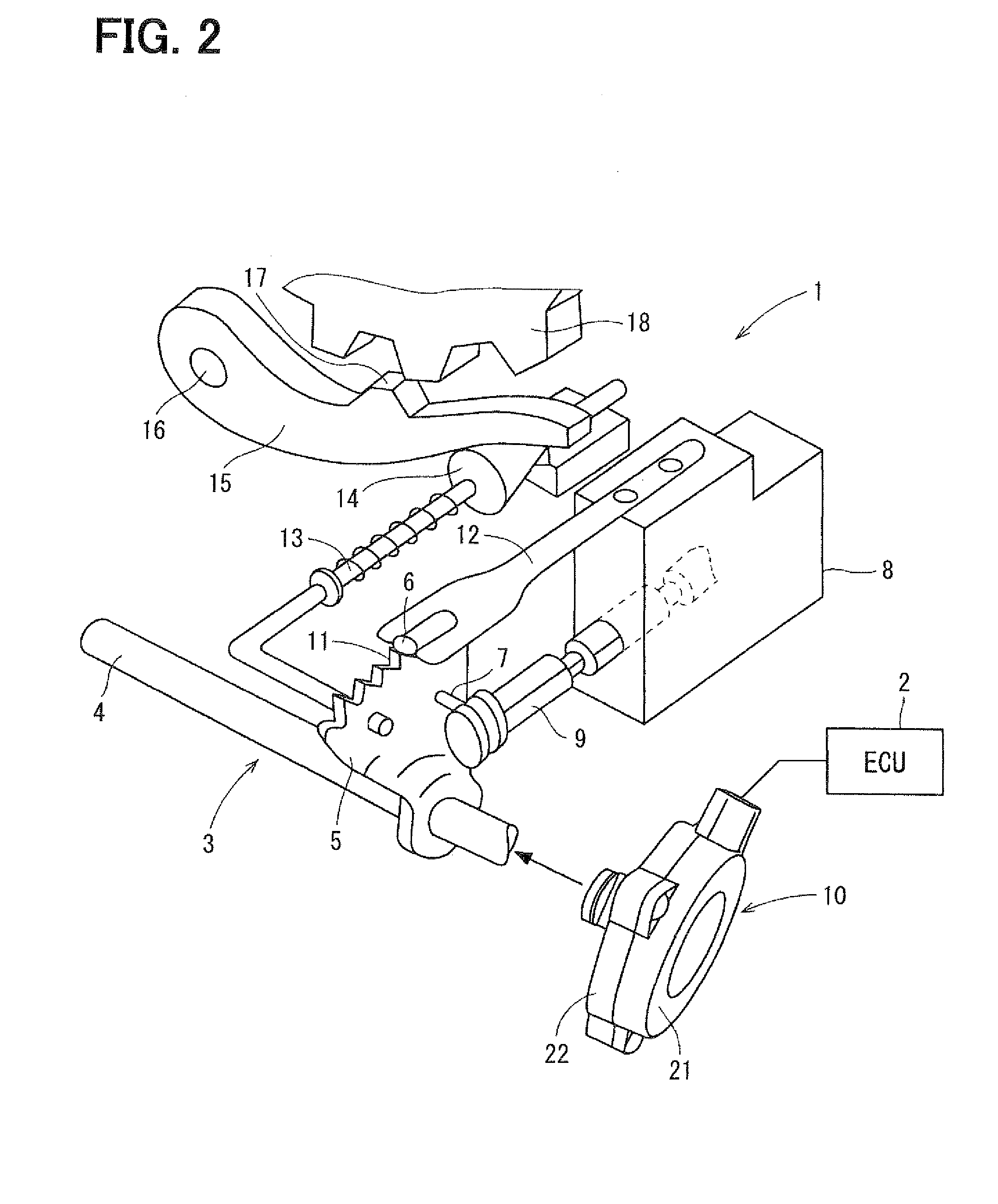
[0020]A rotary actuator according to an embodiment of the present invention will be explained based on the drawings. The rotary actuator according to the present embodiment is applied as a drive section of a shift range switching device 1 that switches a shift range of an automatic transmission of an automobile as shown in FIG. 2. The rotary actuator performs switching drive of the shift range and a parking gear. The shift range switching device 1 has an electronic control unit 2 (ECU) that outputs a drive signal to the rotary actuator 10. The rotary actuator 10 rotates according to the drive signal inputted from the ECU 2 and outputs the rotation to a driving force transmission section 3.

[0021]The driving force transmission section 3 consists of a drive shaft 4, a detent plate 5, a stopper 6 and the like. One end portion of the drive shaft 4 is coupled to an output shaft of the rotary actuator 10 by a spline. The detent plate 5 is formed in the shape of a fan extending ...


PUM

PropertyMeasurementUnit
Magnetic fieldaaaaaaaaaa
Speedaaaaaaaaaa

Abstract

An electric motor drives and rotates a rotor shaft, and a speed reducer reduces speed of rotation of the rotor shaft and outputs the rotation. A shaft is fixed to a front housing. A turning member is meshed with an external teeth member provided to an output shaft of the speed reducer and is supported to be able to rotate around an axis line of the shaft. A turning angle sensor senses a turning angle of the turning member by sensing a magnetic field corresponding to a turning angle of a magnet section provided to the turning member. An outer wall of a cup is fixed to the turning member, and an inner wall of the cup is fitted to a ball bearing. A plate is provided slidably between a bottom outer wall surface of the cup and an end surface of the front housing around the shaft.

Description

CROSS REFERENCE TO RELATED APPLICATION[0001]This application is based on and incorporates herein by reference Japanese Patent Application No. 2009-2716 filed on Jan. 8, 2009.BACKGROUND OF THE INVENTION[0002]1. Field of the Invention[0003]The present invention relates to a rotary actuator that drives a shift range switching device of an automobile and to a manufacturing method of the rotary actuator.[0004]2. Description of Related Art[0005]Conventionally, as a shift range switching device of an automobile, there has been publicly known a shift-by-wire system that senses a shift range, which is selected by a driver, with an electronic control unit (ECU) of a vehicle and that drives and controls a rotary actuator in accordance with the sensing value, thereby switching the shift range of an automatic transmission, for example, as described in Patent document 1 (JP-A-2005-265151).[0006]The applicants of the present application have conceived a scheme of attaching a shift position sensor,...

Claims


Application Information

Patent Timeline
IPC IPC(8): F16H1/00B23P11/00
CPCF16H59/68F16H61/32F16H2061/326Y10T29/49826Y10T74/1836
Inventor KUME, MIKINEYOSHIYAMA, SHIGERU
Owner DENSO CORP
Why Eureka
Try Eureka