
Air Supply Unit

a technology of air supply and air supply, which is applied in the direction of energy-efficient heating/cooling, sustainable buildings, heating fuel, etc., can solve the problem that the efficiency of the heat pump remains unoptimal for heating us

Inactive Publication Date: 2010-07-08
ENERVENT
View PDF12 Cites 36 Cited by
  • Summary
  • Abstract
  • Description
  • Claims
  • Application Information

AI Technical Summary

Benefits of technology

[0006]The object of the invention is to provide an air supply unit that has a relatively simple structure and a compact size, a better temperature efficiency than the prior art air supply units and that can be used efficiently at least for heating supply air.
[0009]The invention is based on that the casing of the air supply unit is provided with a heat pump in addition to a rotating, in other words rotatable, heat exchanger. From hereon, the term “rotating heat exchanger” refers to a rotatable heat exchanger the functioning of which may be based on for instance regenerative heat recovery. By using the heat pump, a better temperature efficiency in comparison to prior air supply unit can be achieved in the air supply unit according to the present invention. The first heat interchanger of the heat pump is adapted to reside in the exhaust air channel between the first inlet and the rotating heat exchanger. Such location for the first heat interchanger provides the advantage that the first heat interchanger resides in such location in the exhaust air stream of the exhaust air channel where the temperature of the exhaust air is the highest, i.e., before the heat exchanger. Therefore, maximum amount of heat energy may be transferred to the refrigerant of the heat pump in heating the supply air.
[0011]The use of rotating heat exchanger of the apparatus according to some embodiments of the present invention may be adapted according to the current use of the air supply unit. For example when cooling supply air and simultaneously heating water using energy extracted from the supply air, the heat exchanger may act as a supplementary cooler of the supply air if the exhaust air is colder than the supply air. If the apparatus is used for cooling supply air only, the rotating heat exchanger may be stopped. Now the transfer of heat through the rotating heat exchanger is prevented without the need of bypassing the heat exchanger by leading the air streams through separate, space-consuming air channels, as would be necessary for example if the air supply unit was equipped with the prior art combination of a heat pump and a plate heat exchanger.

Problems solved by technology

The efficiency of the heat pump thus remains unoptimal for heating use.

Method used


Image

  • Air Supply Unit
  • Air Supply Unit
  • Air Supply Unit

Examples


Embodiment Construction

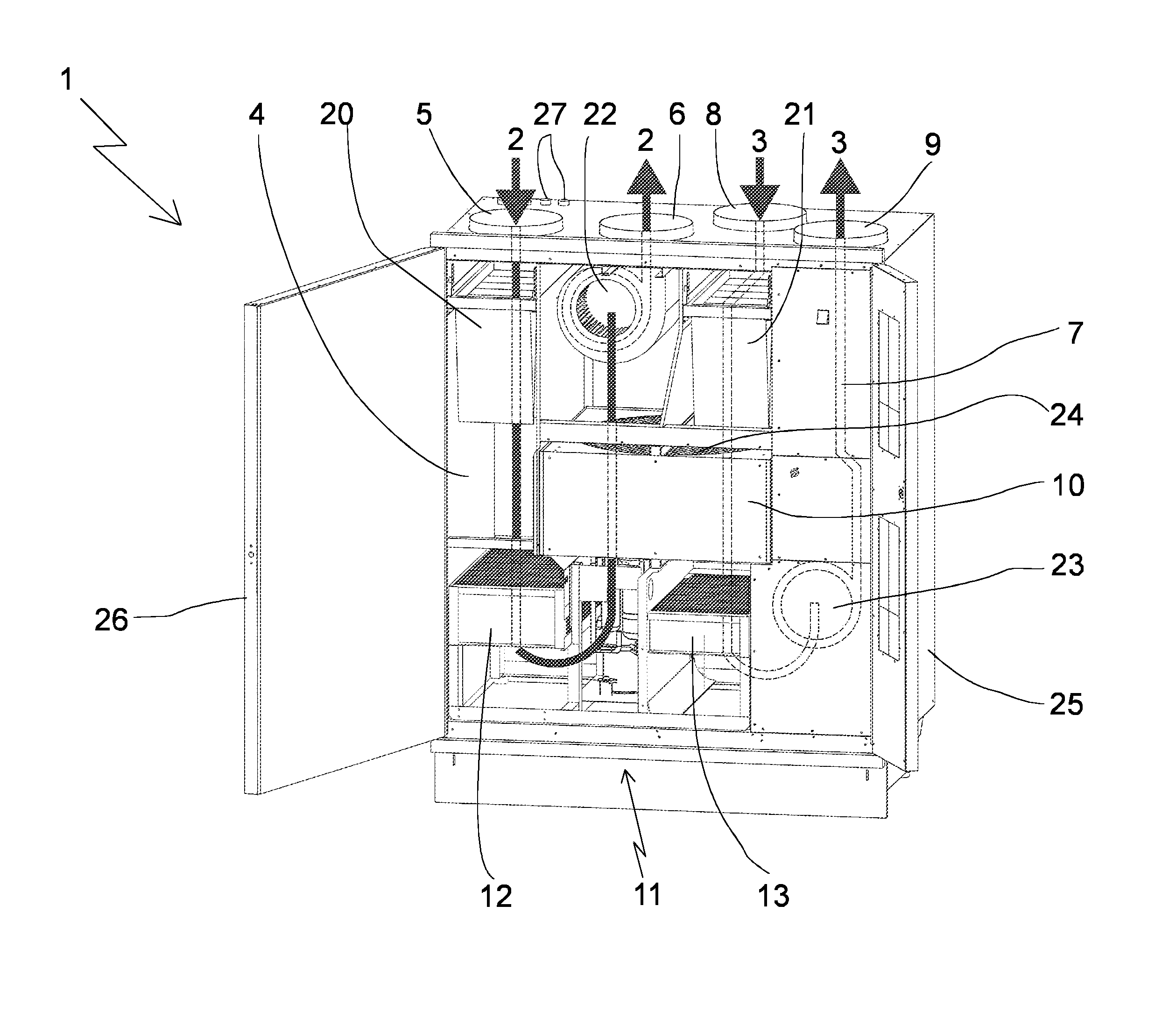
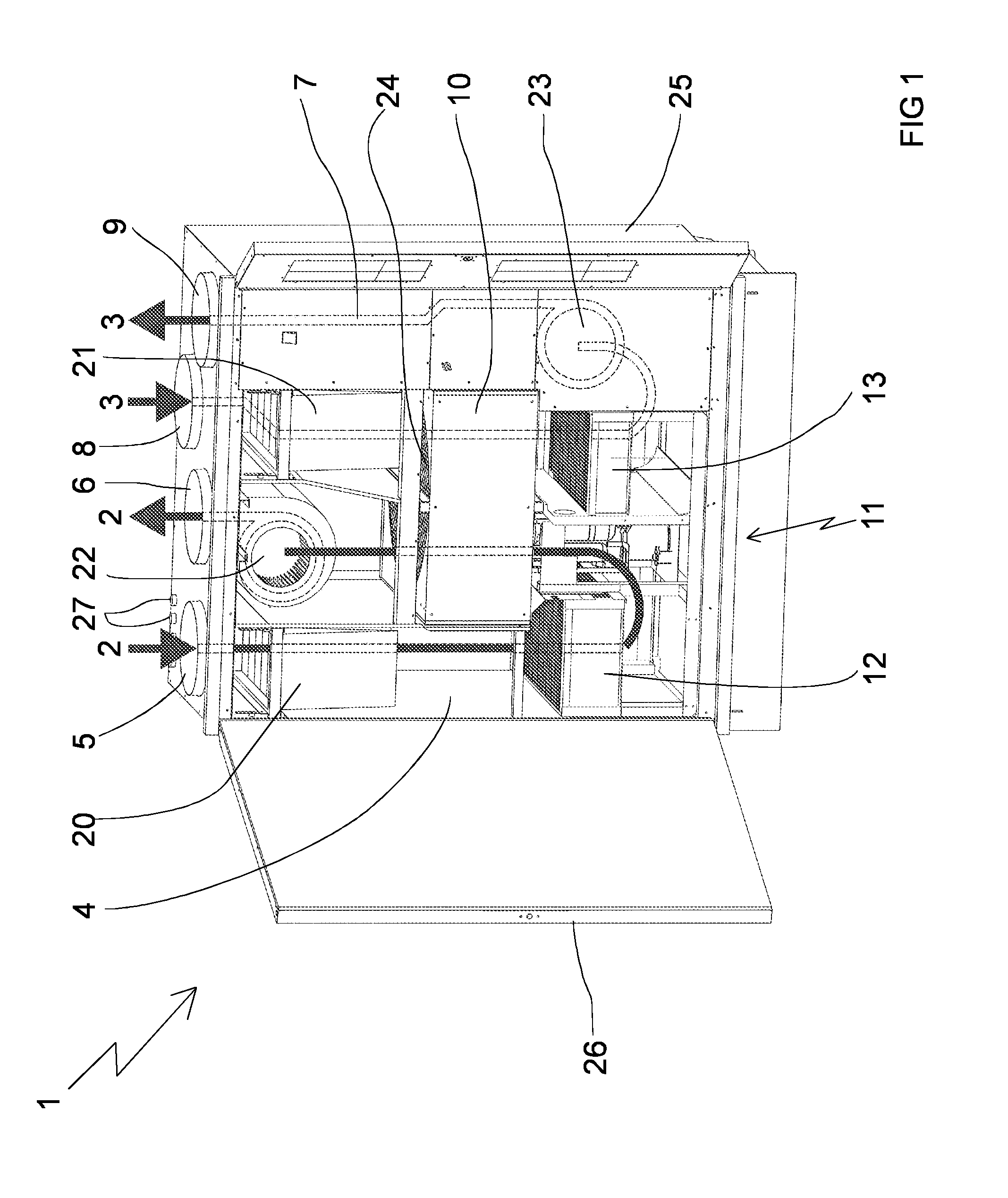
[0028]FIG. 1 depicts an air supply unit 1 for extracting heat energy (not shown in the figures) from exhaust air 2 and transferring the heat energy to supply air 3.

[0029]The air supply unit 1 comprises a casing 25.

[0030]In casing 25, the air supply unit 1 comprises an exhaust air channel 4 for leading exhaust air 2 through the casing 25 of the air supply unit 1.

[0031]The exhaust air channel 4 has a first inlet 5 for leading exhaust air 2 into the exhaust air channel 4 and a first outlet 6 for removing the exhaust air 2 from the exhaust air channel 4. In FIG. 1, the first inlet 5 and the first outlet 6 are equipped with belled pipes (not indicated by a reference number) for connecting the air supply unit 1 for example with air conditioning channels or similar ducts.

[0032]In the air supply unit 1 shown in FIG. 1, the exhaust air channel 4 is composed of the walls, separation walls, bottom and ceiling of the casing 25 of the air supply unit 1. The exhaust air channel 4 of the air suppl...


PUM


Abstract

The object of the invention is an air supply unit (1) for recovering heat energy from an air stream (e.g., exhaust air) and transferring the heat energy to another air stream (e.g., supply air). The air supply unit (1) comprises a casing (25), in the casing (25) an exhaust air channel (4) for leading exhaust air (2) through the casing (25) of the air supply unit (1), in the casing (25) a supply air channel (7) for leading supply air (7) through the casing (25) of the air supply unit (1), and in the casing (25) a heat exchanger (10) for transferring heat energy between the exhaust air (2) flowing in the exhaust air channel (4) that leads through the casing (25) and the supply air (3) flowing in the supply air channel (7). In the casing (25), the air supply unit (1) comprises a heat pump (11) having a first heat interchanger (12) having a first interior for refrigerant, and a second heat interchanger (13) having a second interior for refrigerant. The first heat interchanger (12) is adapted into the supply air channel (4) between the first inlet (5) and the heat exchanger and the second heat interchanger (13) is adapted into the supply air channel (7).

Description

[0001]The object of the invention is an air supply unit for extracting heat energy from a stream of air (e.g. exhaust air) and transferring the heat energy to another stream of air (e.g. supply air) according to the preamble of claim 1.[0002]The air supply unit for extracting heat energy from a stream of air and transferring the heat energy to another stream of air according to the invention is intended for example for heating supply air and / or warm service water, for instance by using heat energy of exhaust air of a building.[0003]Numerous air supply units for heating supply air by using heat energy of exhaust air of a building according to the preamble of claim 1 are previously known. These units are also referred to as air supply units equipped with a heat recovery unit. The common feature of the known air supply units is that they comprise a casing, an exhaust air channel for leading exhaust air through the casing of the air supply unit, a supply air channel for leading supply a...

Claims


Application Information

Patent Timeline
IPC IPC(8): F24F7/007F28D15/00F25B13/00
CPCF24D5/12Y02B30/13F24D17/0005F24D17/02F24D2200/12F24D2200/22F24F12/003F24F12/006F24F2203/1016F24F2203/104F24F2203/1068F24F2203/1084Y02B10/70Y02B30/52Y02B30/563Y02B30/18F24D15/04Y02B30/56
Inventor KRONVALL, PETTERPALMGREN, TOMSODERHOLM, JAN
Owner ENERVENT
Learn More