Receptacles

a technology of connecting box and solar panel, which is applied in the direction of electrical apparatus construction details, pv power plants, coupling device connections, etc., can solve the problems of reducing the life of solar cells, reducing the electrical energy production of solar cells, and unsuitable for present-day high-power solar cells. , to achieve the effect of preventing heat accumulation, reducing the thermal load between the electronic components of the connecting box and the solar panel, and improving cooling

Active Publication Date: 2010-07-08
BELENOS CLEAN POWER HLDG
View PDF8 Cites 6 Cited by
  • Summary
  • Abstract
  • Description
  • Claims
  • Application Information

AI Technical Summary

Benefits of technology

[0019]The connecting slot may be closed by a cover, if required. The cover may be designed such that it actively prevents an encapsulation compound that has been introduced but is not yet cured from running out. For example, this means that it is possible to position a completely prefabricated solar panel independently of the position, immediately after the encapsulation of the connecting slot, without the encapsulation compound flowing out again. This shortens the time required for fitting. The cover is advantageously in the form of a displacer, thus reducing the amount of encapsulation compound required for the encapsulation process. In order to monitor the filling level, the cover may, furthermore, be produced from a transparent material.
[0020]If required, the cover has one or more openings for introduction of an encapsulation compound and for venting. In one embodiment, the cover has two openings, with one of the two being used for filling, and the other for venting. Since, for example, these are arranged diagonally opposite one another and close to the edge of the encapsulation slot, one of the openings is always lower than the other, thus simplifying the filling process. For example, the opening which is located lower can be filled, as a result of which the air that is enclosed can escape from the connecting slot at the opening which is located higher. Another embodiment has a central opening for filling and one or more vent holes at the edge. Other arrangements are possible. If required, the filling openings have so-called connecting stubs which allow connection of a filling apparatus.
[0022]One embodiment of the connecting box is designed such that the rear face of the connecting box does not rest flat on the solar cell, but is held at a certain distance from it by means of the mounting cap. Such raising from the base area has the advantage that the thermal load between the electronic components of the connecting box and the solar panel is reduced. Furthermore, the connecting box may have air guide plates / cooling ribs, which influence the air circulation on the rear face of the box and thus improve the cooling, or prevent heat accumulations. The air guide plates may be produced from the same material as the housing of the connecting box. In order to improve the mechanical robustness and / or to positively influence the air circulation, the air guide plates may be curved, and / or may be used for support on a solar panel in the fitted state. The connecting slot may itself be in the form of a mounting cap. If required, further supports can be provided. The distance between the base area and the rear wall of the connecting box is generally 2-30 mm, although other distances are possible, depending on the embodiment.
[0023]In one embodiment, the mounting cap is segmented such that it projects from the connecting box only on two mutually opposite sides thereof, thus assisting free air circulation. Feet which are parts of the mounting cap as well as the lower edge of the connecting slot are operatively connected to the surface of a solar panel, preferably by adhesive bonding. Air channels can be formed by webs on the housing lower part, and assist convectional cooling. The air guide plates are used to pass the air flow around the connecting slot, thus reducing the risk of heat accumulations. Depending on the position of the solar panel and the position of the connecting box on the solar panel, connecting boxes are used which have the webs aligned approximately parallel to the X axis or Y axis, as a result of which the air flow always passes upwards from the bottom.
[0025]Single-layer or multiple-layer solutions may be provided as a printed circuit board for connection of the electrical / electronic components. In addition to etched printed circuit boards with a copper layer applied on an electrically insulating mount material, it is possible to use a grid produced by stamping from a metal sheet (stamped grid). In one corresponding embodiment, the housing has correspondingly designed holding means, for example in the form of snap-action or clamping connections, for holding the stamped grid. Furthermore, stamped grids have the advantage that they can easily be insert molded together with the electronic components arranged on them, in an injection mold. This makes it possible to ensure that the interior is hermetically sealed. A further advantage is that the heat that is created is dissipated efficiently outward through stamped grids or printed circuit boards which rest on the housing.
[0030]In the situation in which a connecting box is intended to be attached using an adhesive which cures slowly, the time required for processing can be bridged by the use of a supplementary holding means. Good results are achieved by means of double-sided adhesive tape. Depending on the field of application, it is possible to also attach the connecting box exclusively by double-sided adhesive tape. Double-sided adhesive tape allows immediate fixing of the connecting box on a base surface, and this can have a positive influence both on the processing time and on automated processing. Further sealing means may be provided between the connecting box and a base surface.

Problems solved by technology

One problem that arises in this case is that, when a solar cell is partially covered, for example, as a result of a shadow thrown by surrounding objects or by clouds, this solar cell becomes passive and contributes only slightly, if at all, to the electricity production.
In consequence, when connected in series, the current from the adjacent solar cell flows through the covered solar cell, which can thus be damaged or, at least, its life may be reduced.
One particular disadvantage of these arrangements is that they are unsuitable for present-day high-power solar cells, since they have an inadequate cooling.
A further disadvantage is that the proposed encapsulation in silicone unnecessarily increases the material consumption and the weight, and is time-consuming.
One disadvantage of the connecting boxes which are known from the prior art is the inadequate cooling of the electronic components, and the thermal loading of the solar cells which this results in.

Method used


Image

  • Receptacles
  • Receptacles
  • Receptacles

Examples


Embodiment Construction

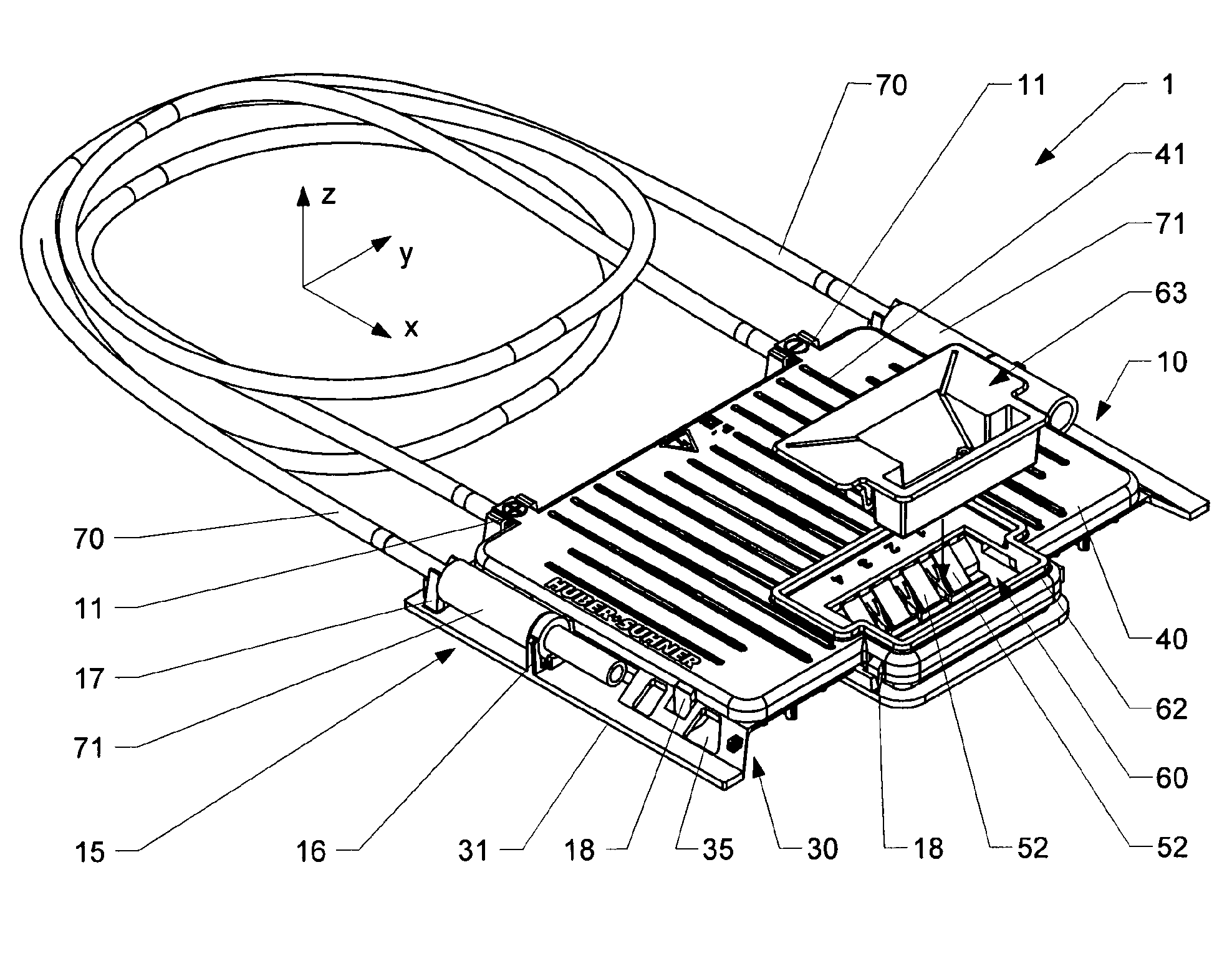
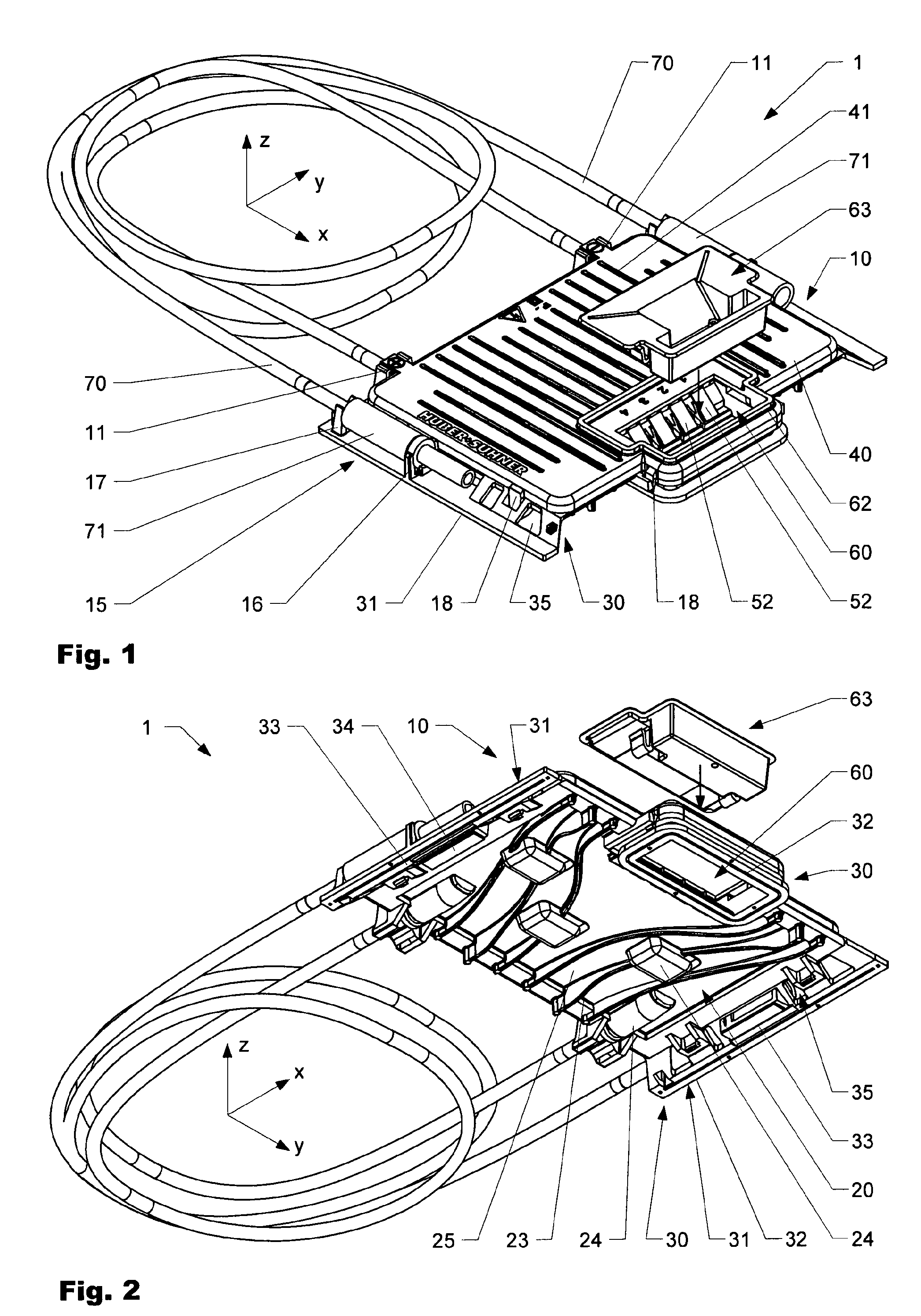
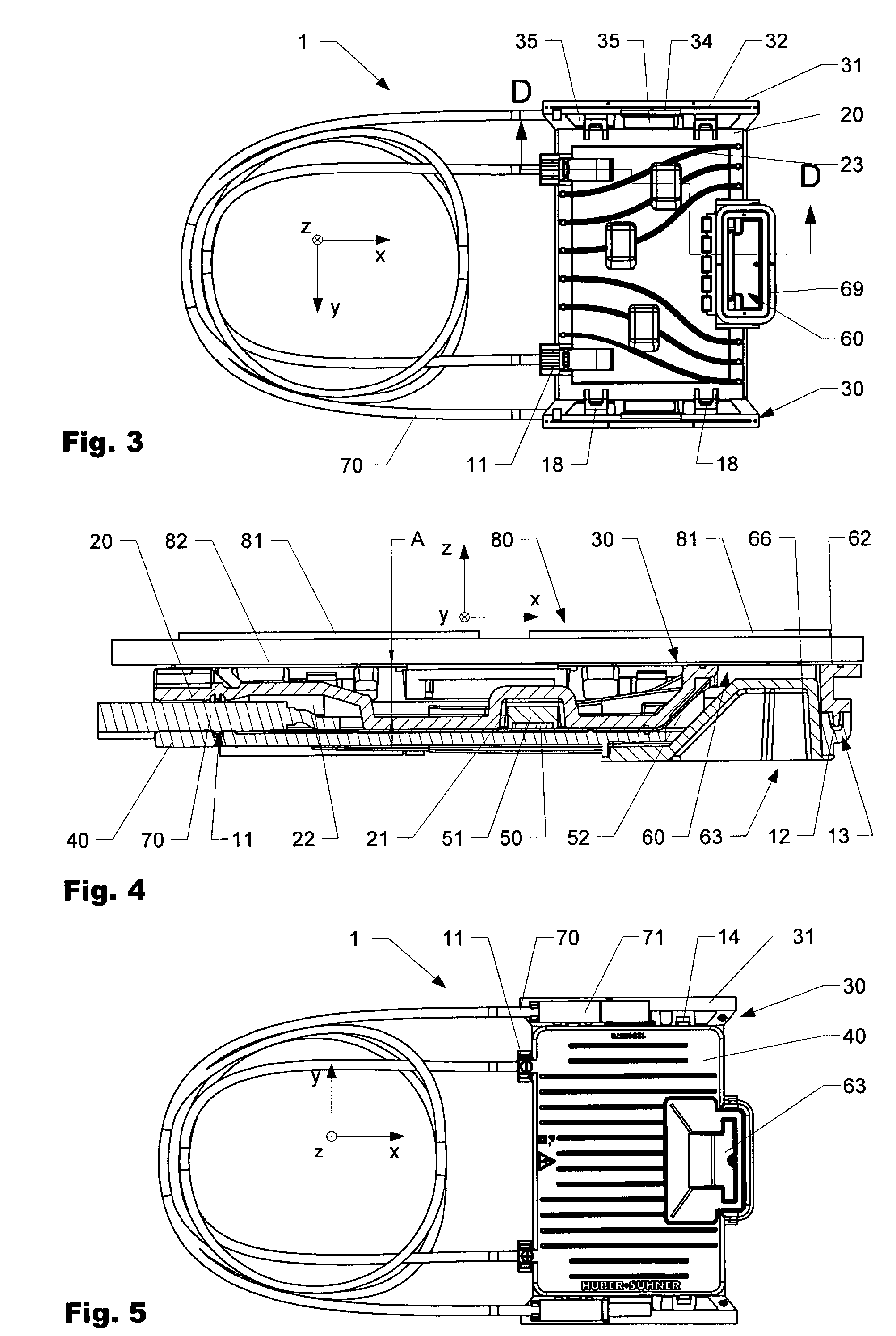
[0039]FIG. 1 shows a perspective illustration of a connecting box 1 obliquely from the front and above, and FIG. 2 shows the same connecting box 1 obliquely from the front and underneath. FIG. 3 shows the connecting box 1 from underneath, FIG. 4 shows a section illustration (section line DD as shown in FIG. 3) from the side, FIG. 5 shows it from above, and FIG. 6 shows it in the open state, obliquely from above.

[0040]The figures show a housing 10, comprising a housing upper part 40 and a housing lower part 20. The two housing parts 20, 40 are in this case connected to one another, inter alia, by means of snap-action tabs 18, that can alternatively or additionally be adhesively bonded to one another, for example, if required. Feet 31 project at the side from the housing 10 and are part of a mounting cap 30 which is segmented here and projects downwards. The mounting cap 30 is used for the actual attachment of the housing 10 to a surface of a solar panel (neither is illustrated in any...


PUM


Abstract

The invention relates to a receptacle (1) particularly suitable for wiring one or more solar cells (81). The receptacle (1) comprises a housing (10) and a connecting shaft (60) that can be separately closed by a cover (63). The receptacle (1) is raised from the back side of the solar panel (80).

Description

BACKGROUND OF THE INVENTION[0001]1. Field of the Invention[0002]The present invention relates to the field of connection technology, and relates in particular to a connecting box for connection of wiring to an appliance, in particular for connection of wiring to a photovoltaic module (photovoltaic collector, solar panel, solar cell).[0003]2. Description of Related Art[0004]Photovoltaic solar installations are generally of modular design and comprise a multiplicity of solar cells which are connected via external wiring. In order to achieve a higher voltage, the individual solar cells are connected at least in groups in series, by the positive pole of a first solar cell being connected to the negative pole of a further solar cell. One problem that arises in this case is that, when a solar cell is partially covered, for example, as a result of a shadow thrown by surrounding objects or by clouds, this solar cell becomes passive and contributes only slightly, if at all, to the electricit...

Claims


Application Information

Patent Timeline
Patent Type & Authority Applications(United States)
IPC IPC(8): H01L31/048
CPCH01R13/502H01R13/52H02S40/34H02S40/345Y02E10/50
Inventor GRIMBERG, THOMASWATERINET, HANNSGOLDI, MAXLEU, SYLVERE
Owner BELENOS CLEAN POWER HLDG
Why Eureka
Try Eureka