Method and apparatus for displaying digital data

a technology of digital data and methods, applied in the field of methods and apparatus for displaying digital data, can solve the problems of limited viewing angle, difficult to achieve, and difficult to achieve the effect of achieving the effect of achieving the effect of achieving the effect of achieving the effect of achieving the effect of achieving the effect of achieving the effect of achieving the effect of achieving the effect of achieving the effect of achieving the effect of achieving the effect of achieving the effect of achieving the effect o

Inactive Publication Date: 2010-07-08
CABANAS MANUEL +1
View PDF8 Cites 28 Cited by
  • Summary
  • Abstract
  • Description
  • Claims
  • Application Information

AI Technical Summary

Benefits of technology

[0012]The present invention provides a new method and apparatus for displaying digital data. More particularly, the present invention comprises the provision and use of a new and improved rotary display which displays the digital data as a 360 degree translucent or transparent “floating” image. To this end, the new rotary display utilizes a vertical array of light-emitting elements which is rotated on an arm about a center axis, and pulsed in an appropriate sequence and at an appropriate rate, so as to present a fixed image to a viewer using the “persistence of vision” phenomenon associated with the human eye. The control electronics are mounted to the rotating arm adjacent to the light-emitting elements. Display content is either pre-loaded to the control electronics, or transferred to the control electronics during device operation, via a wireless (e.g., cellular telephone, Wi-Fi, Bluetooth, etc.) connection. The electrical power for the LED array and the control electronics is provided via a contact-less rotary transformer that functions independently of the rotation speed.

Problems solved by technology

As a result, while there are many applications for such displays, their planar configuration causes them to have a limited viewing angle (i.e., 180 degrees or less).
Thus, efforts have been made to create a cylindrical array of LEDs, however, this approach is relatively expensive and complex due to the large number of LEDs required for the display and the related electronics required to drive those LEDs.
However, all of the rotary displays produced to date suffer from one or more significant limitations.
Among other things, all of the rotary displays produced to date have deficiencies in the manner by which the digital content is uploaded to the rotating portion of the rotary display.
This approach has the advantage that the digital content can be easily loaded into the stationary controller, but it has the disadvantage that the digital content must be transferred from the stationary controller to the rotating portion of the rotary display through an electro-mechanical coupling or through a line-of-sight coupling.
This need to transfer the digital content through such a coupling adds to the complexity of the device, increases cost, increases size, limits installation options and raises reliability issues.

Method used


Image

  • Method and apparatus for displaying digital data
  • Method and apparatus for displaying digital data
  • Method and apparatus for displaying digital data

Examples


Embodiment Construction

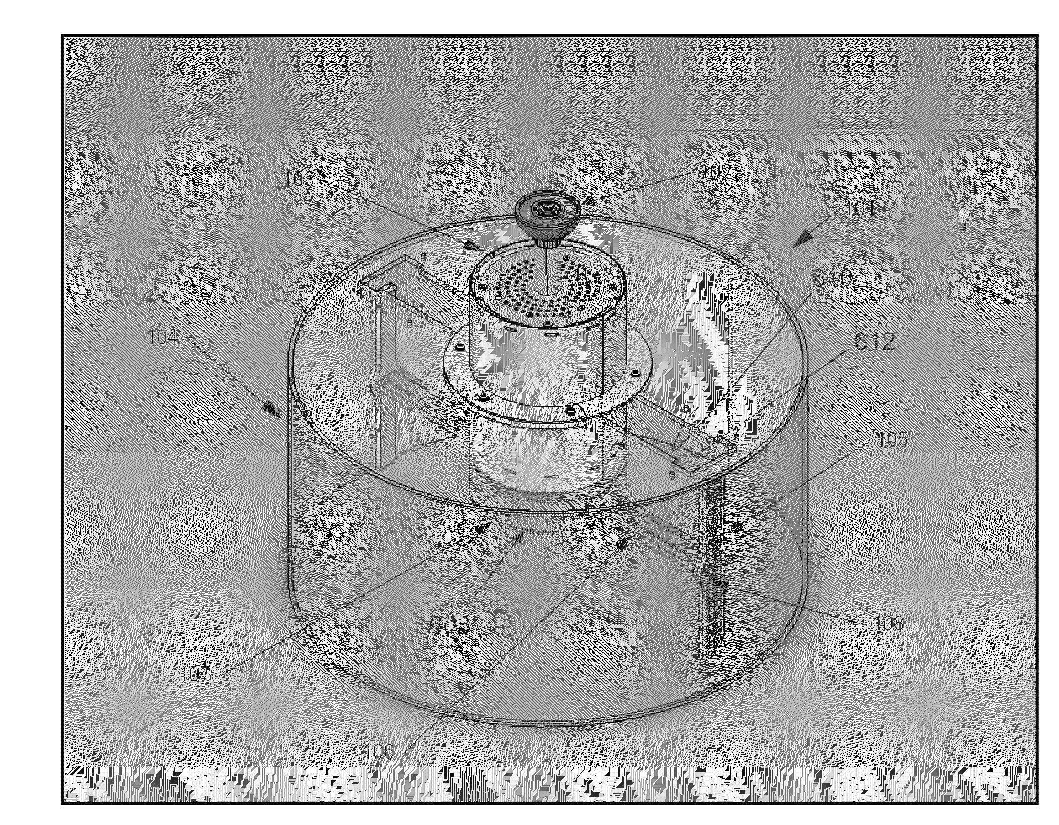
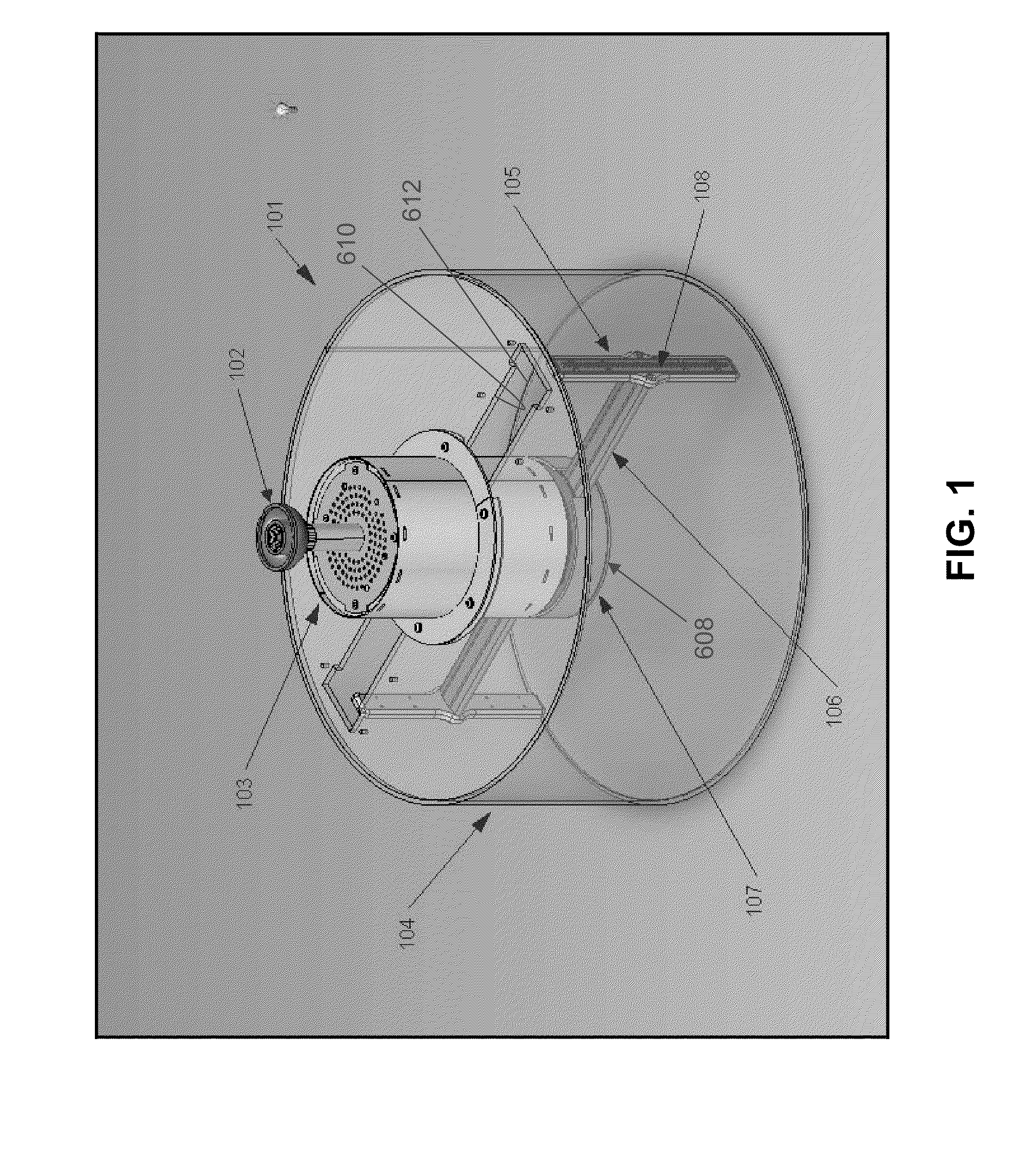
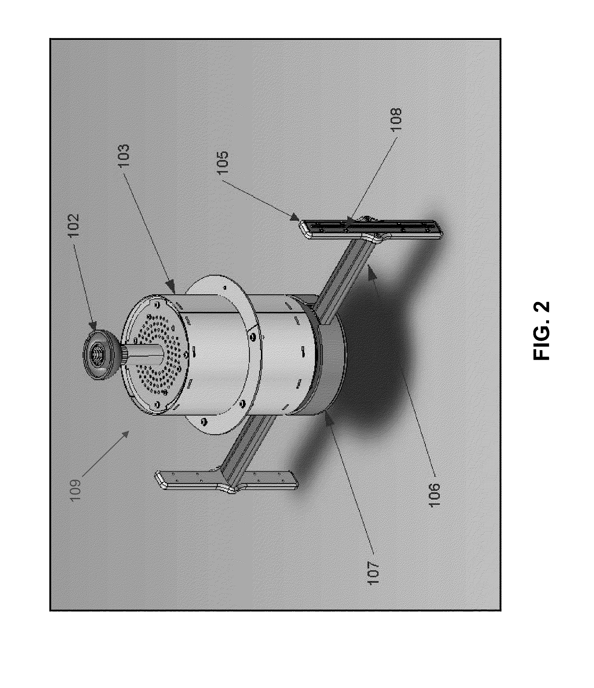
[0038]Looking first at FIGS. 1-3, there is shown a novel rotary display 101 formed in accordance with the present invention. As will hereinafter be discussed in further detail, rotary display 101 is adapted to display digital data as a 360 degree translucent or transparent “floating” image (see FIGS. 9 and 10) and, to this end, comprises a vertical array of light-emitting elements which is rotated on an arm about a center axis, and pulsed in an appropriate sequence and at an appropriate rate, so as to present a fixed image to a viewer using the “persistence of vision” phenomenon associated with the human eye, whereby to provide a 360 degree floating image which is viewable from all angles. The control electronics are mounted to the rotating arm adjacent to the light-emitting elements. Display content is either pre-loaded to the control electronics, or transferred to the control electronics during device operation, via a wireless (e.g., cellular telephone, Wi-Fi, Bluetooth, etc.) con...


PUM


Abstract

A rotary display device comprising one or more vertical arrays of light-emitting diodes (LEDs) are rotated and energized at a controlled rate so as to project a 360 degree floating image. The displayed images are viewable from all angles (i.e., 360 degrees). The LEDs and associated control electronics are rotated at a desired speed, e.g., between about 720 and about 3600 revolutions per minute, by an AC or DC motor. Display content is either pre-loaded to the rotary display or transferred to the rotary display during device operation via a cellular telephone, Wi-Fi, Bluetooth, etc. connection. The electrical power for the system, including the LED array and the control electronics, is provided via a contact-less rotary transformer that functions independently of the rotation speed.

Description

REFERENCE TO PENDING PRIOR PATENT APPLICATION[0001]This patent application claims benefit of pending prior U.S. Provisional Patent Application Ser. No. 61 / 142,492, filed Jan. 5, 2009 by Manuel Cabanas et al. for DIGITAL ROTATING SIGN “DRS”™ DEVICE (Attorney's Docket No. CABANAS-1 PROV), which patent application is hereby incorporated herein by reference.FIELD OF THE INVENTION[0002]This invention relates to methods and apparatus for displaying digital data in general, and more particularly to methods and apparatus for displaying digital data as a 360 degree image.BACKGROUND OF THE INVENTION[0003]Large digital information and entertainment displays based on two-dimensional arrays of light-emitting diodes (LEDs), or other discrete light sources, are well known in the art. These two-dimensional arrays of LEDs are generally arranged in a planar configuration. As a result, while there are many applications for such displays, their planar configuration causes them to have a limited viewing...

Claims


Application Information

Patent Timeline
Patent Type & Authority Applications(United States)
IPC IPC(8): G09G3/00
CPCG09G3/005G03B25/02
Inventor CABANAS, MANUELGREENBERG, HAYLEY
Owner CABANAS MANUEL
Why Eureka
Try Eureka