[0009]In accordance with various embodiments, for example, apparatus and methods are provided for depositing one or more materials on one or more substrates. In various embodiments, such one or more materials can comprise one or more films. In some embodiments, such one or more films can comprise one or more solids. In some embodiments, one or more inks are deposited on one or more substrates.
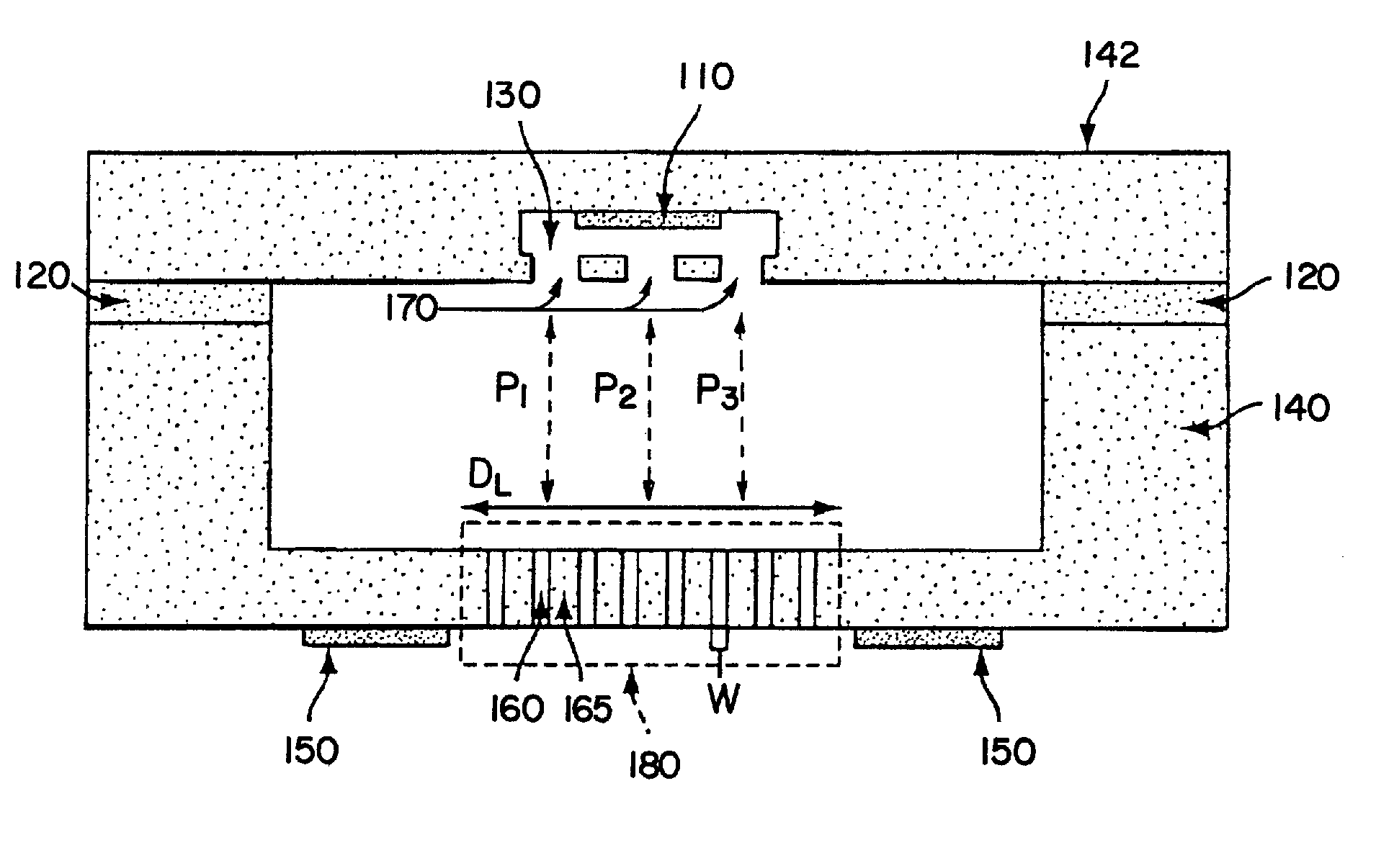
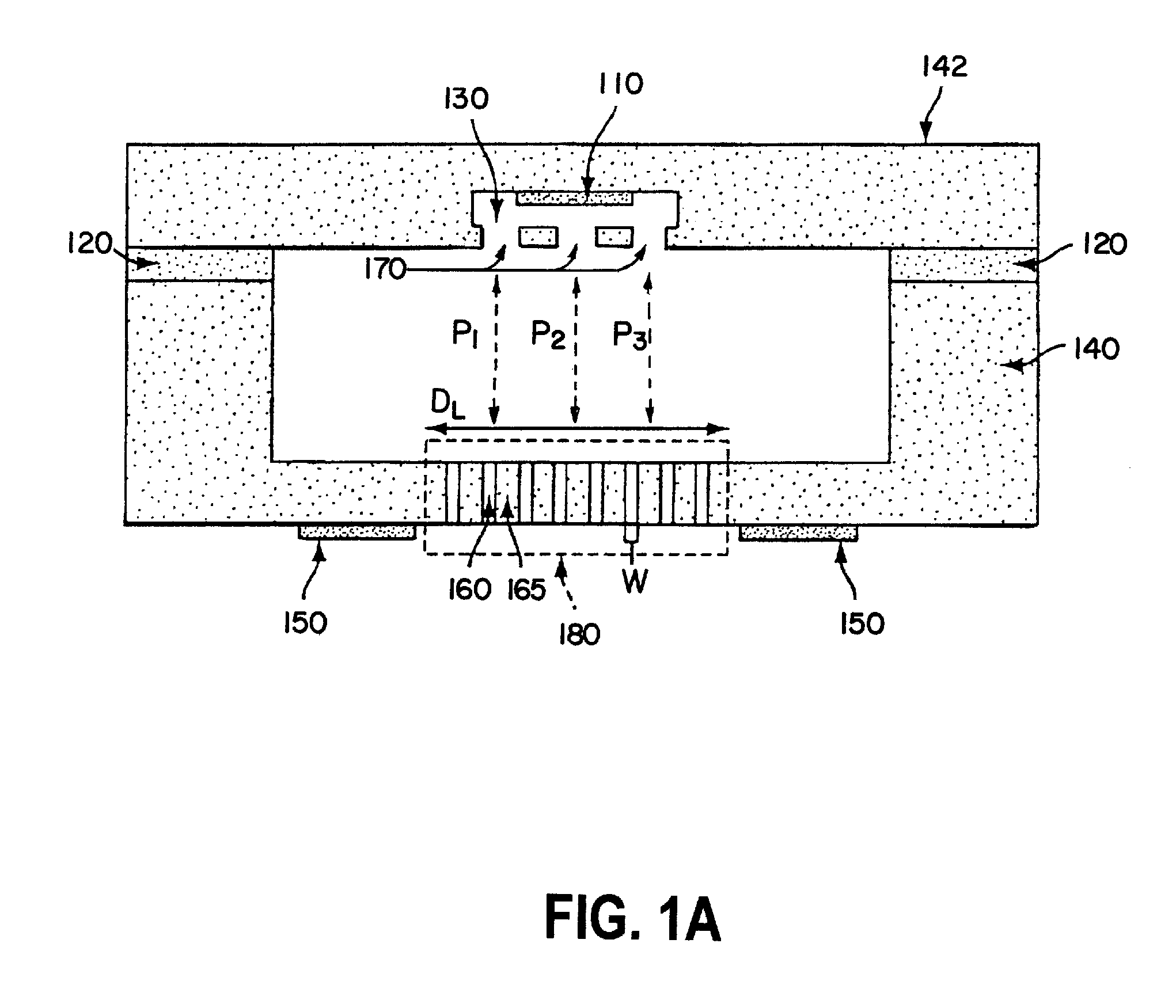
[0010]In accordance with various embodiments, apparatus are provided for depositing one or more materials (e.g., one or more films, such as one or more solids) on one or more substrates. In some embodiments, an apparatus of the present teachings can include one or more of: (i) a chamber for receiving ink; (ii) a discharge nozzle disposed in spaced relation to the chamber and including a plurality of micro-pores, with each micro-pore including a first end region defining an inlet port, confronting the chamber, and a second end region defining an outlet port; and (iii) a plurality of orifices (also referred to as ports) in fluid communication with the chamber, with the orifices being adapted to meter droplets of ink from the chamber along separate respective delivery paths to respective spaced-apart locations on the inlet ports of the discharge nozzle. In various embodiments, the chamber receives ink in liquid form, with the ink being defined by a plurality of substantially solid particles dissolved or suspended in a carrier liquid, and the droplets of ink are pulsatingly metered from the chamber through the orifices to the discharge nozzle; and the discharge nozzle evaporates the carrier liquid and deposits the substantially solid particles on the substrate(s).
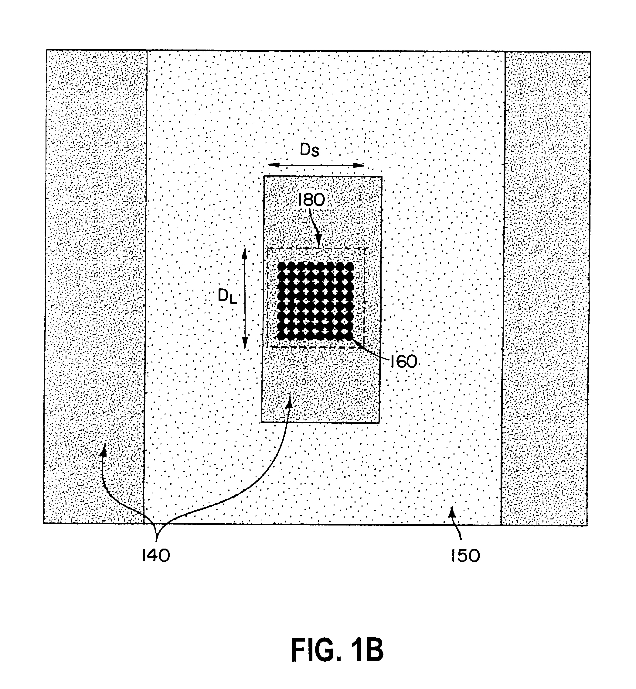
[0011]Further embodiments of apparatus for depositing one or more materials (e.g., one or more films, such as one or more solids) on one or more substrates, in accordance with aspects of the present teachings, can include, for example, one or more of: (i) a chamber configured to hold a liquid, such as liquid ink; (ii) a plurality of orifices disposed for fluid communication with the chamber, the orifices being of a size (e.g., diameter, or cross-sectional area orthogonal to the longitudinal axis of the orifice) to normally prevent the passage of ink therethrough, such as by surface tension forces; (iii) one or more chamber activators (e.g., one or more heater(s) and / or piezoelectric material(s)) operably coupled to the chamber and / or orifices, adapted to provide energy sufficient to substantially simultaneously eject plural droplets of the liquid from the chamber via each orifice of the plurality of orifices (e.g., one droplet from each orifice); (iv) a discharge nozzle disposed in spaced relation to the chamber and including a plurality of micro-pores, which define an array, with each micro-pore including a first end region defining an inlet port, confronting the chamber, and a second end region, facing away from the chamber, defining an outlet port; (v) a plurality of spaced-apart delivery paths, each extending from a respective one of the orifices to a respective, unique location on the inlet ports of the discharge nozzle; and (vi) one or more nozzle activators (e.g., one or more heater(s) and / or piezoelectric material(s)) operably coupled to the discharge array, adapted to provide energy sufficient to discharge the material from the micro-pores, e.g. by heating the micro-pores to one or more selected temperatures and / or through a selected temperature range (e.g., approximately 100 degrees Celsius to approximately 300 degrees Celsius).
[0012]In some embodiments, two or more (e.g., three) orifices are disposed for fluid communication with the chamber, and the micro-pore array defines a rectangle having a long dimension and a short dimension. Further, a line defined by the orifices is disposed parallel to the long axis of the rectangular array. In other embodiments, two or more (e.g., three) orifices are disposed for fluid communication with the chamber, and the array of micro-pores forms a non-rectangular array, such as an array having a chevron or triangular shape. Further, the three orifices are arranged to achieve optimal (e.g., maximal) coverage of the micro-pore array upon ejecting plural droplets of ink from the chamber, along respective delivery paths, and onto the micro-pore array.
[0013]According to various embodiments, methods are provided for depositing one or more materials (e.g., one or more films, such as one or more solids) on one or more substrates. In some embodiments, for example, methods of the present teachings can include one or more of the steps: (a) providing liquid ink to a chamber, the liquid ink defined by a plurality of particles dissolved or suspended in a carrier liquid; (b) pulsatingly energizing at least two spaced-apart orifices, each disposed in fluid communication with the chamber, to substantially simultaneously meter from each orifice a droplet of liquid ink from the chamber; (c) substantially simultaneously passing the metered droplets of ink along separate, respective delivery paths to respective spaced-apart locations on a discharge nozzle; (d) receiving the metered droplets of ink at the discharge nozzle, the discharge nozzle including a plurality of micro-pores for directing the metered droplets of ink; (e) heating the ink at the plurality of micro-pores to evaporate the carrier liquid, thereby rendering said plurality of particles substantially free of carrier liquid; and (f) discharging the plurality of particles from the micro-pores onto the substrate; whereby the plurality of particles are deposited on the substrate(s) in substantially solid form.
[0014]Further embodiments of methods for depositing one or more materials (e.g., one or more films, such as one or more solids) on one or more substrates in accordance with the present teachings can include, for example, one or more of the steps: (a) retaining a volume of liquid ink in a holding region, with the liquid ink comprising a plurality of particles dissolved or suspended in a carrier liquid; (b) delivering energy (e.g., thermal and / or mechanical) to the holding region, thereby substantially simultaneously ejecting a plurality of droplets of liquid ink from at least two spaced-apart locations along the holding region such that each droplet is passed along a respective delivery path to a unique location along a plane adjacent the holding region; (c) subdividing each of the ejected droplets into a plurality of micro-volumes of liquid ink, each micro-volume disposed in a respective micro-holding region immediately adjacent the plane; (d) heating the micro-holding regions to a first temperature (e.g., 100 degrees Celsius) such that the carrier liquid evaporates, thereby providing solid particles in the micro-holding regions that are substantially free of carrier liquid; (e) heating the micro-holding regions to a second temperature (e.g., 300 degrees Celsius) such that the solid particles therein are vaporized into a gas; and (f) directing the gas out of the micro-holding regions (e.g., by application of energy, such as heat and / or mechanical) and onto a substrate adjacent thereto, upon which it solidifies. In various embodiments, a film is thereby formed.

