Sealed Lubrication System and Method for Dynamic Stabilization System

a dynamic stabilization system and sealant technology, applied in the field of sealant lubrication system for dynamic stabilization system, can solve the problems of affecting the loading environment of the disc, affecting the stability of the disc,

Inactive Publication Date: 2010-07-08
CUSTOM SPINE INC
View PDF4 Cites 12 Cited by
  • Summary
  • Abstract
  • Description
  • Claims
  • Application Information

AI Technical Summary

Benefits of technology

[0005]In view of the foregoing, an embodiment herein provides a dynamic screw assembly including a fixation component that connects to a vertebral body, the fixation component includes at least one inlet to allow a lubricant to pass inside the fixation component, a ring member coupled to the fixation component, a stopper sealing at least one inlet, a coupling member includes an inwardly curved bottom portion and a bulbous end extending from the inwardly curved bottom portion, a bumper mechanism coupled to the fixation component and the coupling member, a longitudinal member coupled to the coupling member, and a blocker that retains the longitudinal member in the coupling member. The ring member prevents the lubricant from leaking out of the fixation component. The bulbous end includes at least one groove that houses the lubricant, and at least one slot to allow the bulbous end to fit into the fixation component and limit a range of angulation of the coupling member with respect to the fixation component.
[0006]A saddle connection is inserted through the bulbous end of the coupling member and may be extended to the fixation component, and a spring member coupled to the saddle connection. The spring member provides a continuous upward force on the saddle connection. The saddle connection prevents disengaging of the coupling member from the fixation component. The longitudinal member connects to a plurality dynamic screw assemblies.
[0008]Another embodiment herein provides an apparatus for dynamic stabilization of a vertebral column. The apparatus includes a lubricant having material properties that reduce friction and increase wear resistance of objects in connection with the lubricant, a bone anchor including an open concave head, an inlet, and a groove, a ring member coupled to the bone anchor, a coupling member including a pair of arms that are diametrically opposed, the pair of arms including a U-shaped slot positioned between the pair of arms and an inwardly curved bottom portion of the coupling member, and an outwardly protruding and expandable bulbous end extending from the inwardly curved bottom portion, and a hole positioned extending from the inwardly curved bottom portion and through the bulbous end, a bumper mechanism coupled to the fixation component and the coupling member, a saddle connection that is engaged in the hole of the coupling member and connects to the bone anchor, a longitudinal member engaged in the U-shaped slot, a spring member coupled to the saddle connection, a stopper connected to the bone anchor, and a threaded blocker that engages the pair of arms of the coupling member and secures the longitudinal member in the U-shaped slot.
[0009]The inlet allows the lubricant to pass inside the bone anchor. The ring member prevents leakage of the lubricant from the groove. The bulbous end is seated inside the open concave head of the bone anchor. The bumper mechanism is shaped to accommodate a predetermined range of angulation of the fixation component with respect to the coupling member. The spring member continuously pushes up the engaged saddle connection. The stopper seals the lubricant in the groove of the bone anchor.
[0012]A stopper may be inserted in the aperture. The stopper prevents the lubricant from escaping from the bone fixation component. The longitudinal member may be connected to a plurality of dynamic screw assemblies. A spring member may be positioned inside the bone fixation component and against the saddle connection. The spring member provides a continuous upward force on the saddle connection. The bone fixation component includes a reservoir positioned in at least one of a location of the spring member and on a side of the bone fixation component to house the lubricant. The bulbous end includes at least one groove to house the lubricant. The blocker retains the longitudinal member in the coupling member.

Problems solved by technology

Intervertebral disc degeneration often leads to chronic lower back pain.
This may be due to abnormal loading patterns on the disc.
Rigid spinal instrumentation restricts the motion but alters the loading environment of the disc away from the dynamic stabilization systems.
This leads to a lot of wear and tear due to friction between the rough base materials of the dynamic stabilization systems.

Method used


Image

  • Sealed Lubrication System and Method for Dynamic Stabilization System
  • Sealed Lubrication System and Method for Dynamic Stabilization System
  • Sealed Lubrication System and Method for Dynamic Stabilization System

Examples


first embodiment

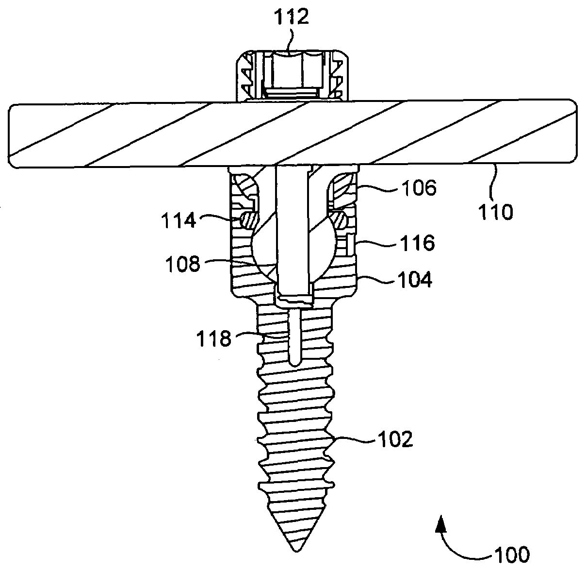
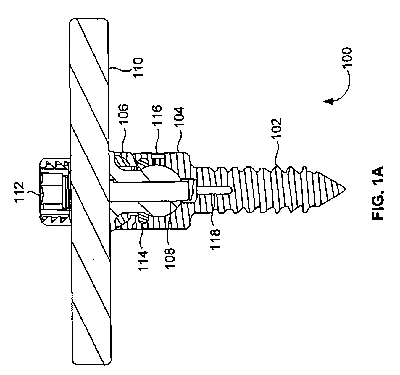
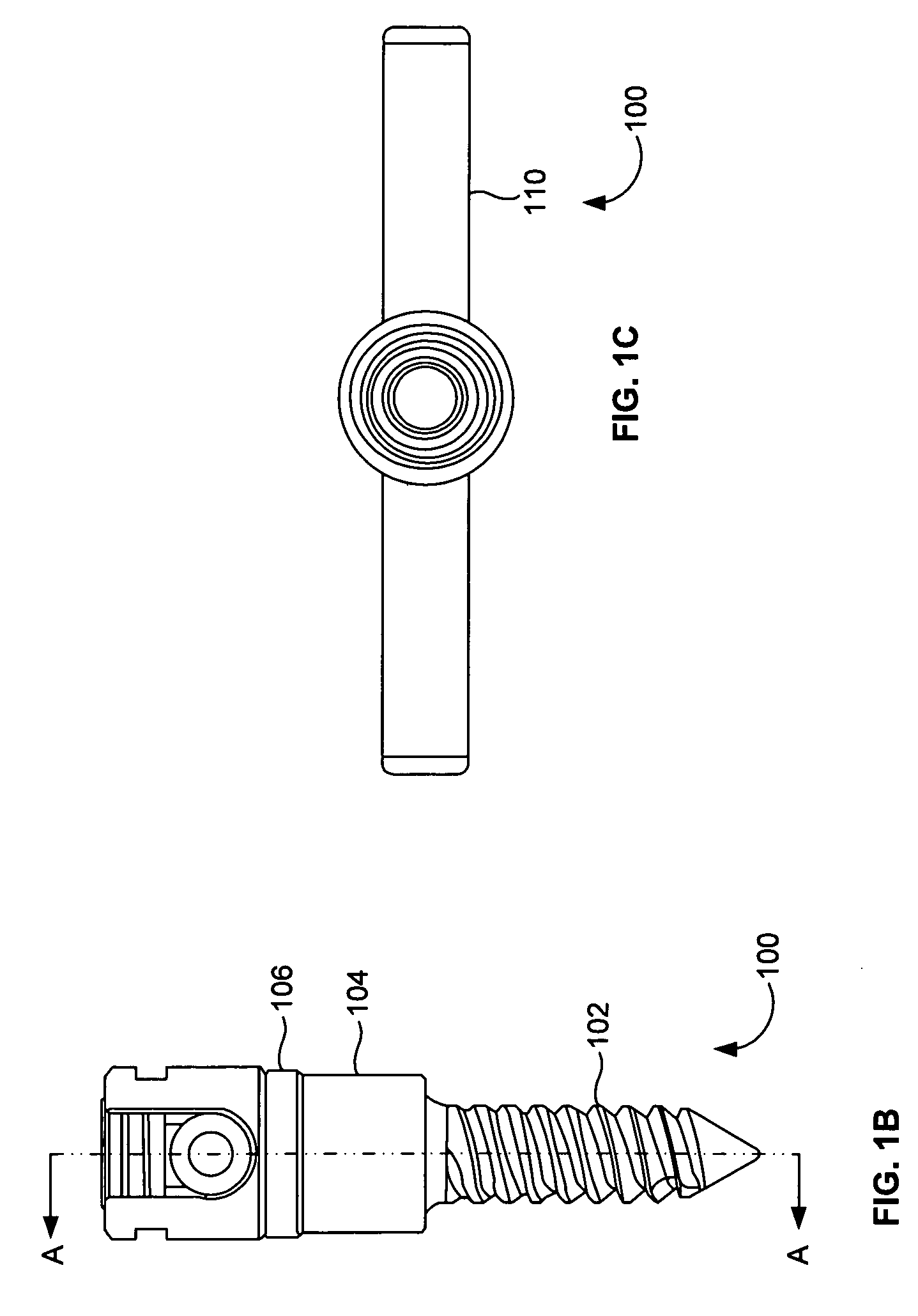
[0040]FIGS. 7A through 7D illustrate a perspective view, a front view, a cross-sectional view, and a top view, respectively, of the bumper 106 of the dynamic screw assembly 100 of FIGS. 1A through 1C herein. In this embodiment, the biased bumper 106A is configured as a bowl-shaped mechanism 115 with an open top 113 and bottom 117. The top 113 bottom 117 of the biased bumper 106 may be beveled to provide the biasing effect.

second embodiment

[0041]FIGS. 8A through 8D illustrate a perspective view, a front view, a cross-sectional view, and a top view, respectively, of the bumper 106 of the dynamic screw assembly 100 of FIGS. 1A through 1C herein. In this embodiment, the biased bumper 106B is configured as a bowl-shaped mechanism 127 with an open top and bottom. A slot 128 is included in the mechanism 127. The upper surface 129 and lower surface 130 of the biased bumper 106C may be angled to provide the biasing effect.

third embodiment

[0042]FIGS. 9A through 9D illustrate a perspective view, a front view, a cross-sectional view, and a top view, respectively, of the bumper 106 of the dynamic screw assembly 100 of FIGS. 1A through 1C herein. In this embodiment, the biased bumper 106C comprises a generally flat top portion 181 with a central bore 121 having a raised surface 125 extending outwardly from the top portion 181. A curved bottom portion 123 of the bumper 106C is defined by opposed curved legs 119, which provides the biasing effect.

[0043]The biased bumper 106 is located between the bone anchor 102 and the coupling member 104. In one embodiment, the bumper 106 coincides with the range of angulation created by the dynamic screw assembly 100.

[0044]FIGS. 10A through 10D illustrate a perspective view, a front view, a cross-sectional view, and a top view, respectively, of the ring member 114 of the dynamic screw assembly 100 of FIGS. 1A through 1C according to an embodiment herein. The ring member 114 fits into t...


PUM


Abstract

A dynamic screw assembly includes a fixation component that connects to a vertebral body, the fixation component includes at least one inlet to allow a lubricant to pass inside the fixation component, a ring member coupled to the fixation component, a stopper sealing at least one inlet, a coupling member includes an inwardly curved bottom portion and a bulbous end extending from the inwardly curved bottom portion, a bumper mechanism coupled to the fixation component and the coupling member, a longitudinal member coupled to the coupling member, and a blocker that retains the longitudinal member in the coupling member. The bulbous end includes at least one groove that houses the lubricant, and at least one slot to allow the bulbous end to fit into the fixation component and to limit a range of angulation of the coupling member with respect to the fixation component.

Description

BACKGROUND[0001]1. Technical Field[0002]The embodiments herein generally relate to a dynamic stabilization system, and, more particularly, to a sealed lubrication system for a dynamic stabilization system.[0003]2. Description of the Related Art[0004]Intervertebral disc degeneration often leads to chronic lower back pain. This may be due to abnormal loading patterns on the disc. Degenerative disc disease may be treated by restricting the motion of the spine to a range where near normal disc loading occurs. Rigid spinal instrumentation restricts the motion but alters the loading environment of the disc away from the dynamic stabilization systems. Systems such as inter spinous process spacers, pedicle screws, and facet replacement products are hence used to maintain the ideal physiologic state of the disc. In dynamic stabilization systems, there is movement between components of the system along with natural movements of the spine. This leads to a lot of wear and tear due to friction b...

Claims


Application Information

Patent Timeline
Patent Type & Authority Applications(United States)
IPC IPC(8): A61B17/04A61B17/70
CPCA61B17/7037
Inventor ABDELGANY, MAHMOUD F.OH, YOUNG HOON
Owner CUSTOM SPINE INC
Why Eureka
Try Eureka