Air-conditioning system

a technology of air-conditioning system and air-conditioning capability, which is applied in the direction of heating types, instruments, static/dynamic balance measurement, etc., can solve the problems of marked decrease of air-conditioning capability, marked decrease of comfort in the room, and insufficient air-conditioning capability for the entire indoor space, so as to achieve energy-saving operation efficiently

Active Publication Date: 2010-07-08
MITSUBISHI ELECTRIC CORP
View PDF23 Cites 27 Cited by
  • Summary
  • Abstract
  • Description
  • Claims
  • Application Information

AI Technical Summary

Benefits of technology

[0009]In addition, the conventional air conditioner has a problem in that since each of the air conditioners operates independently, multiple air conditioners simultaneously perform defrosting operation during a heating operation, so that temporarily the air-conditioning capability markedly decreases and markedly lowers the level of comfort in the room.
[0012]According to the above described air-conditioning system, an energy-saving operation can be realized efficiently.

Problems solved by technology

A conventional air conditioner has a problem in that an indoor unit detects whether any human is present in each of air-conditioning areas and independently air-conditions each of the air-conditioning areas, and for example when many people are concentrated in a certain area of the room, the air conditioner in an area with no people operates under a power-saving operation mode, so that the air-conditioning capability becomes insufficient for the entire indoor space.
If a shift amount to a power-saving operation is made uniformly small to prevent such a problem as described above, it is difficult to sufficiently obtain a power-saving effect.
In addition, the conventional air conditioner has a problem in that since each of the air conditioners operates independently, multiple air conditioners simultaneously perform defrosting operation during a heating operation, so that temporarily the air-conditioning capability markedly decreases and markedly lowers the level of comfort in the room.

Method used


Image

  • Air-conditioning system
  • Air-conditioning system
  • Air-conditioning system

Examples


first embodiment

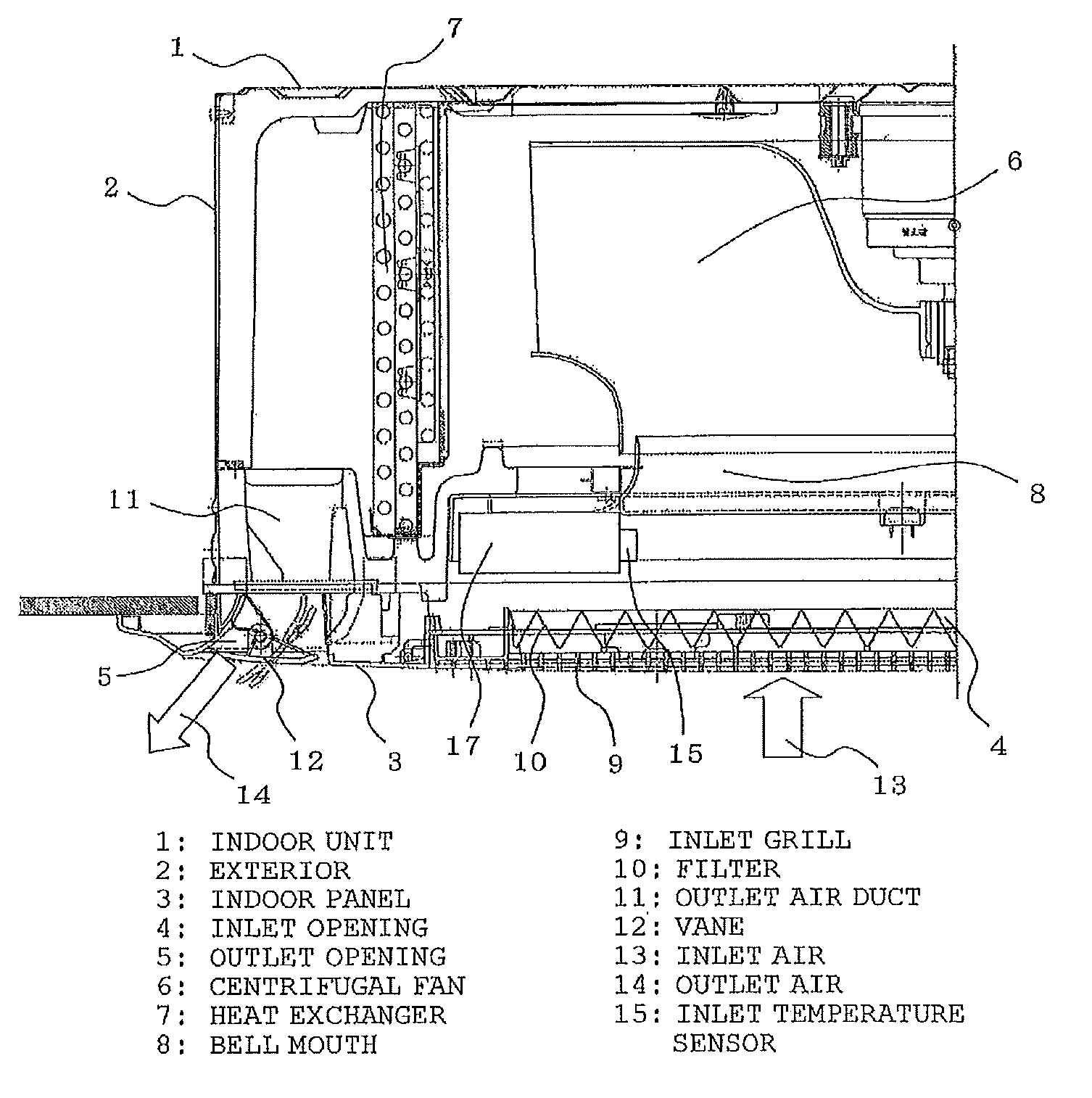
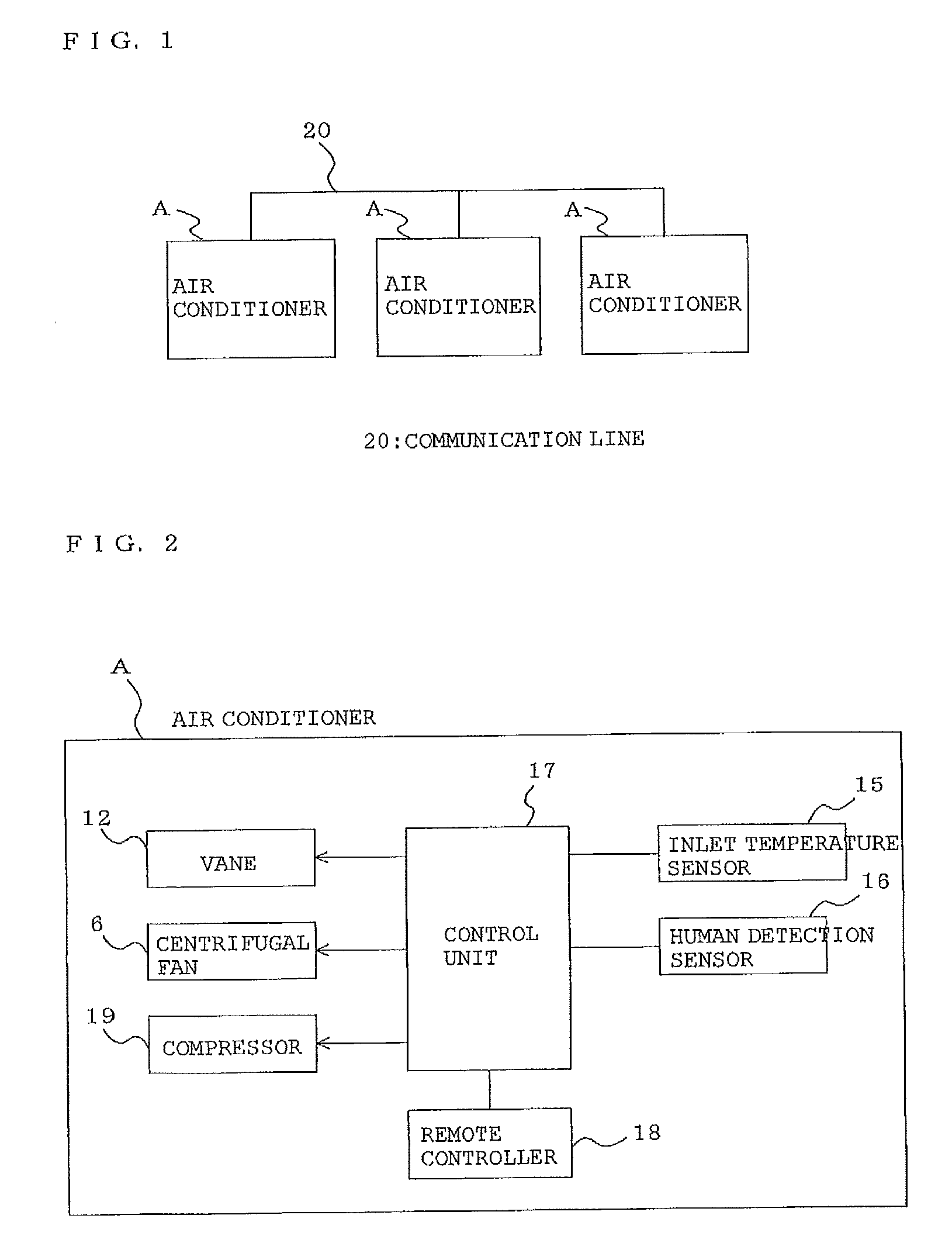
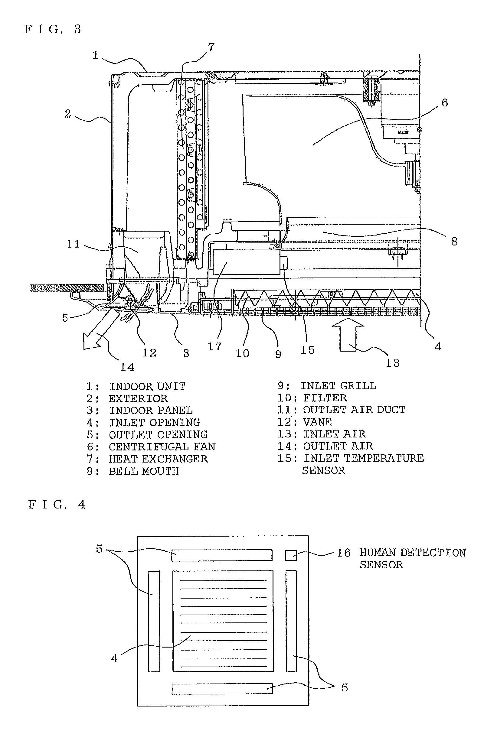
[0019]FIG. 1 is a block diagram of an air-conditioning system according to the first embodiment of the present invention. FIG. 2 is a block diagram showing the internal configuration of the air conditioner of the air-conditioning system. FIG. 3 is a cross sectional diagram showing the configuration of half of the entire indoor unit of the air conditioner of the air-conditioning system. FIG. 4 is a front elevational view showing an indoor panel of the air conditioner of the air-conditioning system.

[0020]An indoor unit 1 of an air conditioner A of the air-conditioning system according to the present embodiment 1 is a ceiling-embedded type embedded in the ceiling of the room, but can also be applied to an indoor unit of other embodiments.

[0021]As shown in FIG. 3, the indoor unit 1 has a rectangular box-shaped outer shell 2 embedded on the upper side of a ceiling 50 and a rectangular planar indoor panel 3 attached to the lower end opening of the outer shell 2 from the indoor side.

[0022]...

second embodiment

[0088]FIG. 5 is a block diagram of an air-conditioning system according to the second embodiment of the present invention.

[0089]In the above-described first embodiment, the control units 17 of multiple air conditioners A independently operate on the basis of all of the detection information in the same indoor space. In the second embodiment, as shown in FIG. 5, the control units 17 of the air conditioners A are connected via the communication line 20 in such a manner that one of the three air conditioners A installed in the same indoor space serves as a parent device.

[0090]Therefore, the control unit 17 of the air conditioner A serving as the parent device can grasp the detection information of the human detection sensor 16 of the other two air-conditioners A, the preset temperature information of the remote controller 18, and the inlet temperature information of the inlet temperature sensor 15, and on the basis of the above-mentioned information calculates the air-conditioning load...

third embodiment

[0091]FIG. 6 is a block diagram of an air-conditioning system according to the third embodiment of the present invention.

[0092]In the third embodiment, as shown in FIG. 6, a control apparatus 30, which is different from the three air conditioners A installed in the same indoor space, is connected to the control units 17 of all of the air conditioners A and the communication line 20 so as to serve as a host.

[0093]Therefore, the control apparatus 30 can grasp the detection information of the human detection sensor 16 of the three air conditioners A, the preset temperature information of the remote controller 18, and the inlet temperature information of the inlet temperature sensors 15, and on the basis of the above-mentioned information, calculates the air-conditioning load of each of the air-conditioning target spaces and the air-conditioning load of the entire air-conditioning space based on the air-conditioning loads of these air-conditioning target spaces. The control apparatus 30...


PUM


Abstract

Control units for three indoor units of air conditioners installed in a same indoor space are connected by a communication line. Each of the control units can grasp the detection information of the human detection sensor, preset temperature information of the remote controller, inlet temperature information of the inlet temperature sensor of all of the other air conditioners in the same space. On the basis of the above-mentioned information, each of the control units calculates an air-conditioning load of each of the air-conditioning target spaces and the air-conditioning load of an entire air-conditioning space on the basis of these air-conditioning target spaces in the same manner. A compressor is driven and controlled on the basis of a calculation result thereof to perform a power-saving operation of the entire air-conditioning space.

Description

BACKGROUND OF THE INVENTION[0001]1. Field of the Invention[0002]The present invention relates to an air-conditioning system for controlling a plurality of air conditioners arranged in an indoor space and having a human detection sensor on an indoor unit to detect the human motion.[0003]2. Description of the Related Art[0004]An air conditioner of this kind has been developed, wherein the main body is attached with an infrared sensor for detecting the human motion (hereinafter referred to as a human detection sensor) and the air conditioner is capable of power-saving operation by turning off the operation or shifting the preset temperature to the power-saving side upon detection by this human detection sensor whether any human is present (for example, see Japanese Unexamined Patent Application Publication No. 2008-101880 (page 1, FIG. 1)).[0005]As described above, with the use of the human detection sensor, the operation mode of the air conditioner can be automatically controlled acco...

Claims


Application Information

Patent Timeline
Patent Type & Authority Applications(United States)
IPC IPC(8): G05B15/00F24F11/02F24F11/04
CPCF24F11/0034F24F2011/0046F24F3/065F24F2011/0067F25B2600/0253Y02B30/741F24F11/0012F24F11/30F24F2110/10F24F2120/10F24F2140/50F24F11/54Y02B30/70F24F11/62F24F11/46F24F11/86
Inventor TAKAGI, MASAHIKOBABA, MASANOBUISHIKAWA, NORIKAZU
Owner MITSUBISHI ELECTRIC CORP
Why Eureka
Try Eureka