
System and method for providing virtual interface

a virtual interface and system technology, applied in the field of user interface of computer system, can solve the problems of no method of interfacing with a user, difficult for a computer system to operate in high speed, and inability to provide the user interface simultaneously to both programs

Inactive Publication Date: 2010-07-08
MOON CHANG SUN +1
View PDF4 Cites 8 Cited by
  • Summary
  • Abstract
  • Description
  • Claims
  • Application Information

AI Technical Summary

Benefits of technology

[0004]The present invention has been developed in order to solve the above and other problems associated with the conventional device, and an object of the present invention is to provide a system and a method for providing a virtual interface which is capable of providing a user interface independent of an operating system without assignment of screen resources from the operating system in a computer system.

Problems solved by technology

However, since response speed and processing speed of peripheral devices cannot be realized as fast as that of the central processing unit while fast data processing is realized by the central processing unit, it is difficult for a computer system to operate in high speed.
However, if one application program uses exclusively screen resources in an operating system providing a multitasking environment, other application program has no method of interfacing with a user through the single display screen which is possessed exclusively by the one application program because the other application program cannot be assigned the screen resources which have been already possessed exclusively.
Of course, the other application program can be activated by inactivating the corresponding application program executed in the exclusive mode and thus canceling the exclusive mode, however it is impossible to provide the user interface simultaneously to both programs when the corresponding application program is executed in the exclusive mode.

Method used


Image

  • System and method for providing virtual interface
  • System and method for providing virtual interface
  • System and method for providing virtual interface

Examples


Embodiment Construction

[0020]The present invention, an operational advantage thereof and an object thereof achieved by an embodiment thereof will be sufficiently appreciated with reference to accompanying drawings illustrating preferred embodiment of the present invention and the description thereof. The embodiment of the present invention may be modified to various forms and it should not be appreciated that the embodiment to be described in below limits the scope of the present invention. The present embodiment is just for explaining the present invention more specifically to those skilled in the art. Further, known functions and constructions irrelevant to the subject matter of the present invention will not be described. Hereinafter, the embodiments of the present invention will be described in detail with reference to accompanying drawings.

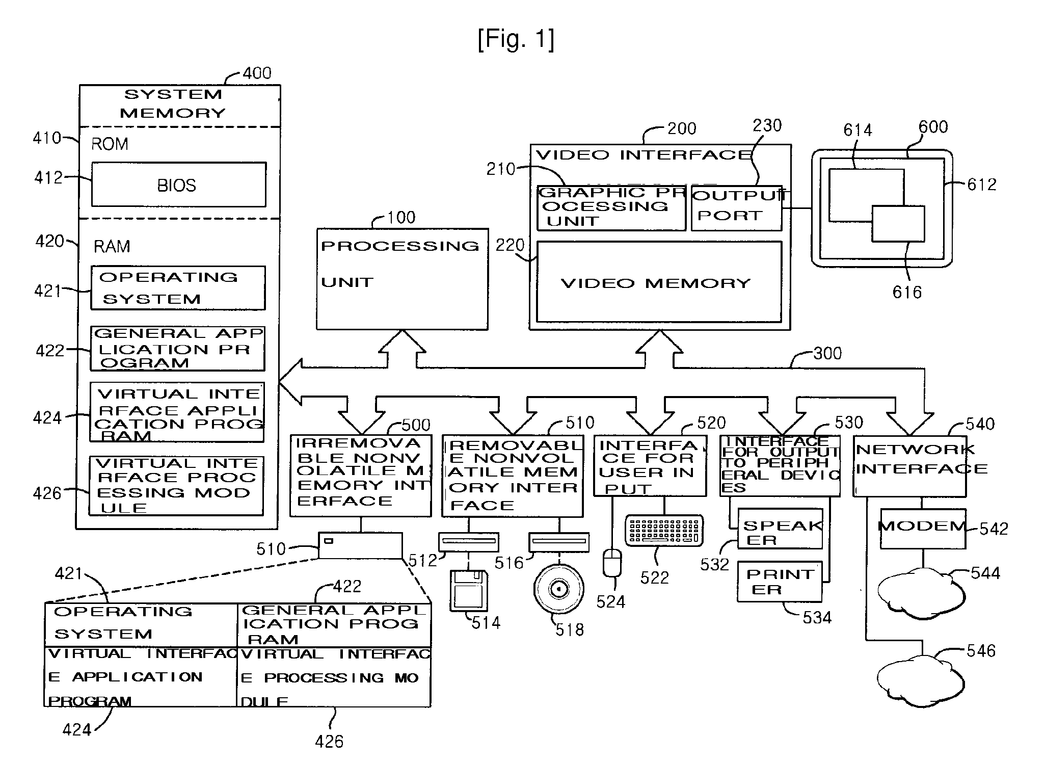
[0021]FIG. 1 is a block diagram illustrating a computer system provided with a virtual interface according to a preferable embodiment of the present invention.

[002...


PUM


Abstract

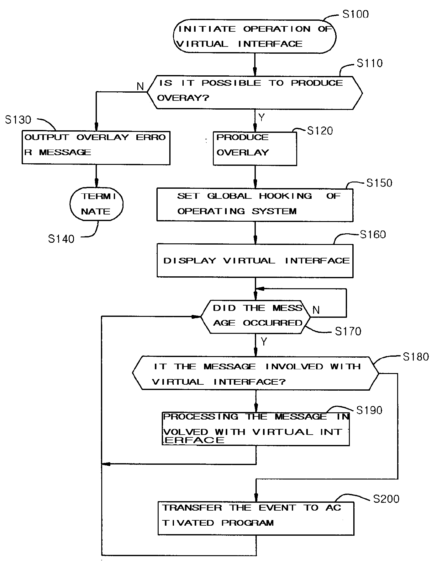
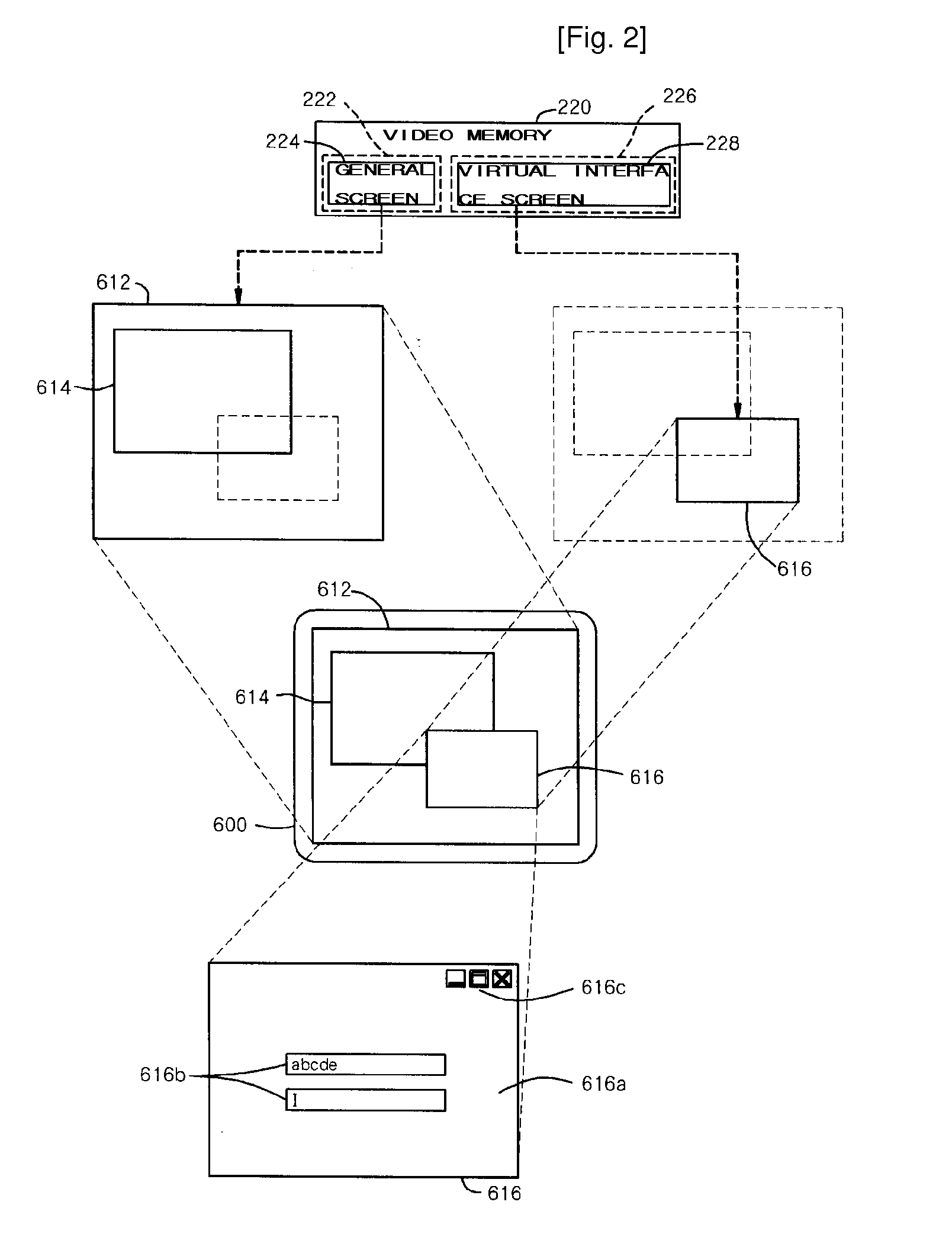
A system and a method of the present invention output a virtual interface screen to the display using independent video output channel which is not directly involved with the operating system. An embodiment for realizing the virtual interface uses an overlay function and the other uses a miniport function. In the case of using the overlay function, an overlay area in the video memory is used as the independent video output channel for displaying the virtual interface screen. In the case of using the miniport function, a part of commonly used general area in the video memory is used as the independent video output channel for displaying the virtual interface screen. The virtual interface of the present invention outputs a virtual interface screen independently of the operating system using an overlay function or a miniport function thereby providing the virtual interface screen to a display screen without assignment of screen resources from the operating system.

Description

TECHNICAL FIELD [0001]The present invention relates to a user interface of a computer system, and more particularly, to a system and a method for providing a new type virtual interface for providing a user interface independent of an operating system.BACKGROUND ART[0002]Recently, rapid development of hardware and software of a computer enables various applications using a computer in every field of society. For example, computers have been applied in general business, online banking, playback of multimedia, online game, data communication, etc. Processing speed of computers has been raised more and more by repeated improvement of operation frequency of a central processing unit. However, since response speed and processing speed of peripheral devices cannot be realized as fast as that of the central processing unit while fast data processing is realized by the central processing unit, it is difficult for a computer system to operate in high speed. In order to solve this problem, tec...

Claims


Application Information

Patent Timeline
IPC IPC(8): G06F3/14
CPCG09G5/14G06F2009/45579G06F9/45558G06F9/4445G06F9/452G06F3/14G06F13/00
Inventor MOON, CHANG SUNPYO, SE JIN
Owner MOON CHANG SUN
Learn More