Method of displaying multi-channel waveforms

a multi-channel waveform and waveform technology, applied in the field of image communication, can solve the problems of reducing the performance of the whole system, affecting the performance of the chip, and affecting the performance of the whole system, so as to improve achieve excellent extensibility, high system efficiency, and the effect of reducing the performance of the chip

Active Publication Date: 2006-07-20
SHENZHEN MINDRAY BIO MEDICAL ELECTRONICS CO LTD
View PDF6 Cites 39 Cited by
  • Summary
  • Abstract
  • Description
  • Claims
  • Application Information

AI Technical Summary

Benefits of technology

[0009] The present invention is directed to provide a method of displaying multi-channel dynamical waveforms on a display device simultaneously at a high efficiency with a low cost for embedded system, in order to solve the inconsistency between the increase of waveforms and the resultant significant increase of logic resources and degradation of the performance of chips for display, enabling an excellent extensibility of the system.
[0010] Accordingly, the present invention is conceived according to the following conception. In a system in which a control circuit is implemented by FPGA or ASIC (application specific integrated circuit), waveforms under changes and text and interface information under relatively few changes are processed separately so as to improve the efficiency of displaying. Further, information of a waveform screen which contains multi-channel waveforms under changes may be processed with the waveform screen being divided into multiple waveform screens, which enable dynamic display of the multi-channel waveforms in parallel in a same region on the display terminal. In order to refresh or scroll in different rate the multi-channel waveforms under changes respectively in different horizontal regions and in different windows of a same horizontal region in a same waveform screen independently, the system establishes a parameter table in a memory for the waveform screen to define parameters of waveforms of each channel, such as display mode, boundary of a window and so on, so that waveforms of each channel may have different boundaries and different rates of refreshing and scrolling, resulting in increased flexibility of the arrangement of waveforms. Furthermore, switching delay resulted in the switching of waveform parameters may be significantly lowered by means of the parameter table in the memory rather than by means of MUX, thereby dynamic display of the multi-channel waveforms could be realized at a high efficiency with a low cost, meanwhile the extensibility of the system may be improved.
[0016] According to the technical solution above mentioned, the system will be advantageous in that the efficiency of processing the display of multi-channel waveforms can be improved and an excellent extensibility can be achieved.
[0023] According to the second technical solution above mentioned, the waveform parameter table does not occupy register resources in FPGA, so the inconsistency between the increase of waveforms and the resultant significant increase of logic resources and degradation of the performance of chips for display could be relieved, enabling an excellent extensibility and high efficiency of the system in terms of the display of multi-channel waveforms.

Problems solved by technology

With this method, when a waveform is scrolled, it is necessary for CPU to erase the whole waveform being displayed and overwrite all of the refreshed waveform data to the video memory so as to perform the moving of the waveform, thus leading a very heavy load of CPU.
In a case of displaying multi-channel waveforms simultaneously, expenses of software in the system will be significantly increased so that the whole performance of the system is degraded.
Consequently, this method has no advantage in efficiency despite of high cost.
The other aspect lies in degradation of the performance of the chip for display with the increase of channels of waveforms, because the system usually requires higher display resolution to cope with the increase of the waveforms, which means that the highest operation frequency of the chip for display should be improved.
If the number of inputs of MUX is large, the switching delay will be considerably large, resulting in degradation of the highest operation frequency of the chip for display.
Consequently, it is difficult for existing solution to support such a display where waveforms of more than 7 channels are scrolled simultaneously.
Furthermore, there is no solution provided in the prior art for the display of multi-channel waveforms in a same region in parallel.

Method used


Image

  • Method of displaying multi-channel waveforms
  • Method of displaying multi-channel waveforms
  • Method of displaying multi-channel waveforms

Examples


Embodiment Construction

[0030] For better understanding of the present invention, preferable embodiments of the present invention will be described below with reference to the attached drawings.

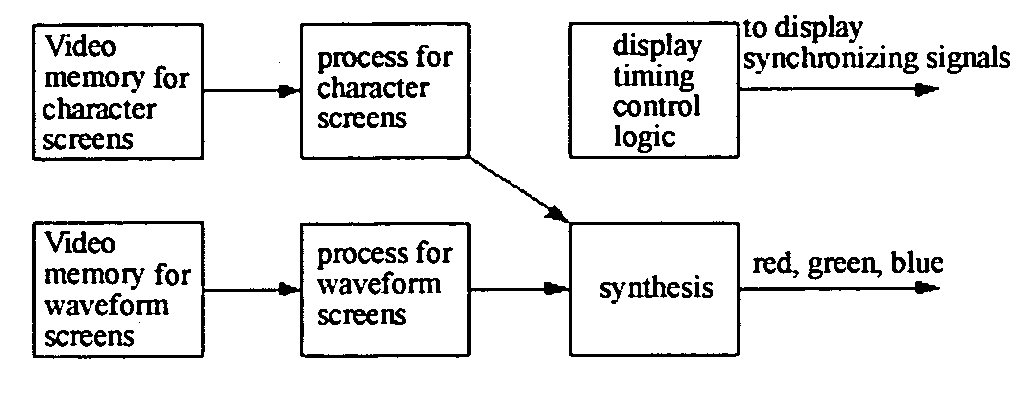
[0031] Taking into account of the characteristics that text information such as menus, alert, help and so on are usually required for an embedded system, the basic configuration of a display drive circuiting according to the present invention is shown in FIG. 1, which is capable of improving the efficiency of the system in terms of processing the display of multi-channel waveforms. For the reason of different requirements for dynamical display of waveforms and relatively stationary display of text information, character information and waveforms displayed physically on the same display terminal may be defined as a character screen and a waveform screen that are separated logically. That is, separate spaces may be assigned in a video memory for storing character data and waveform data respectively, accordingly writi...


PUM


Abstract

A method of displaying multi-channel waveforms, which is used for displaying multi-channel waveforms dynamically in embedded systems, the method comprising the steps of: dividing at least one waveform screen in a video memory which is mapped to a display terminal into a plurality of waveform windows, wherein boundaries of each of the windows are defined by a plurality of values set in at least a set of boundary registers; establishing a waveform parameter table in a memory of the system, which contains characteristic parameters of each waveform in each of the waveform windows; writing waveform data into a logical space in the waveform screen corresponding to a waveform by writing operations from CPU to the video memory; and on a basis of the parameters of the waveform windows in the waveform parameter table, performing a display mode defined by the parameter by means of is changing the mapping relationship between the video memory and the display terminal, before transmitting the data of each of the waveform windows read out from the video memory to the display terminal by a display drive circuit. According to the method of present invention, the inconsistency between the increase of waveforms and the resultant significant increase of logic resources and degradation of the performance of chips for display can be solved, which enables the system advantageous in high efficiency, low cost and excellent extensibility.

Description

BACKGROUND OF THE INVENTION [0001] The present invention generally relates to a technique for displaying in a field of image communication, particularly to a method of displaying multi-channel waveforms in embedded systems. [0002] A medical patient monitor is typically an embedded system, which is necessary to support displaying multi-channel waveforms. In such system, physiological signals of a human body, such as ECG (electrocardiograph), SPO2 (Pulse Oxygen Saturation) and NIBP (non-invasive blood pressure) and so on, are measured by sensors and detection circuit, then physiological parameter values are obtained which will be recorded in waveform after being subjected to a calculation process, and finally displayed in real time on display terminals such as CRT (cathode-ray tube) and LCD (Liquid Crystal Display). In general, display terminals of patient monitors are required of supporting high-resolution (above 640*480) color displaying and employing display interfaces with special...

Claims


Application Information

Patent Timeline
Patent Type & Authority Applications(United States)
IPC IPC(8): G06F19/00
CPCG06F19/3406G16H40/63
Inventor YAO, LICHEN, WEI
Owner SHENZHEN MINDRAY BIO MEDICAL ELECTRONICS CO LTD
Why Eureka
Try Eureka