
Bandless cabinet packaging design

Inactive Publication Date: 2010-07-15
THIRD DIMENSION +1
View PDF10 Cites 1 Cited by
  • Summary
  • Abstract
  • Description
  • Claims
  • Application Information

AI Technical Summary

Benefits of technology

[0009]The improved design allows a cabinet or other article to be shipped in a cap or upper packaging member and base tray or lower packaging member without using conventional bands or banding to hold the package together.
[0013]Another aspect of the present disclosure is security strips or bands also include a flap at opposite ends that inserts through a corresponding slot defined in the cap and base members. The strips or bands help prevent damage or access to the cabinet.
[0016]Still another aspect of the new packaging design is that there can be no damage from a band or banding (as sometimes occurs in conventional band-type packaging), particularly to the article (e.g. a cabinet) secured by the packaging design.
[0017]Another aspect of the disclosure is that the lack of bands removes a trip hazard at the location where the package is opened.
[0018]Still another aspect of the packaging design is it has a much cleaner look, such as compared to a conventionally banded package.

Problems solved by technology

Bands which hold the two pieces (upper and lower boxes) of the package together can cause damage to the article or cabinet secured by the packaging design.
Bands also can cause a trip hazard at the location where the package is opened.

Method used


Image

  • Bandless cabinet packaging design
  • Bandless cabinet packaging design
  • Bandless cabinet packaging design

Examples


Embodiment Construction

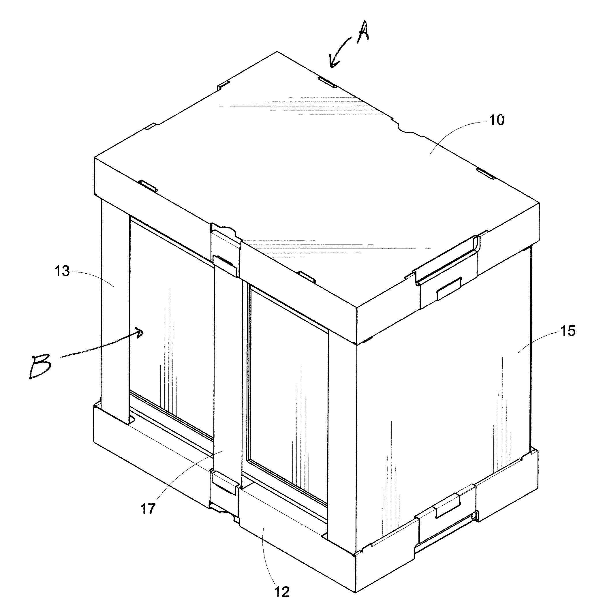
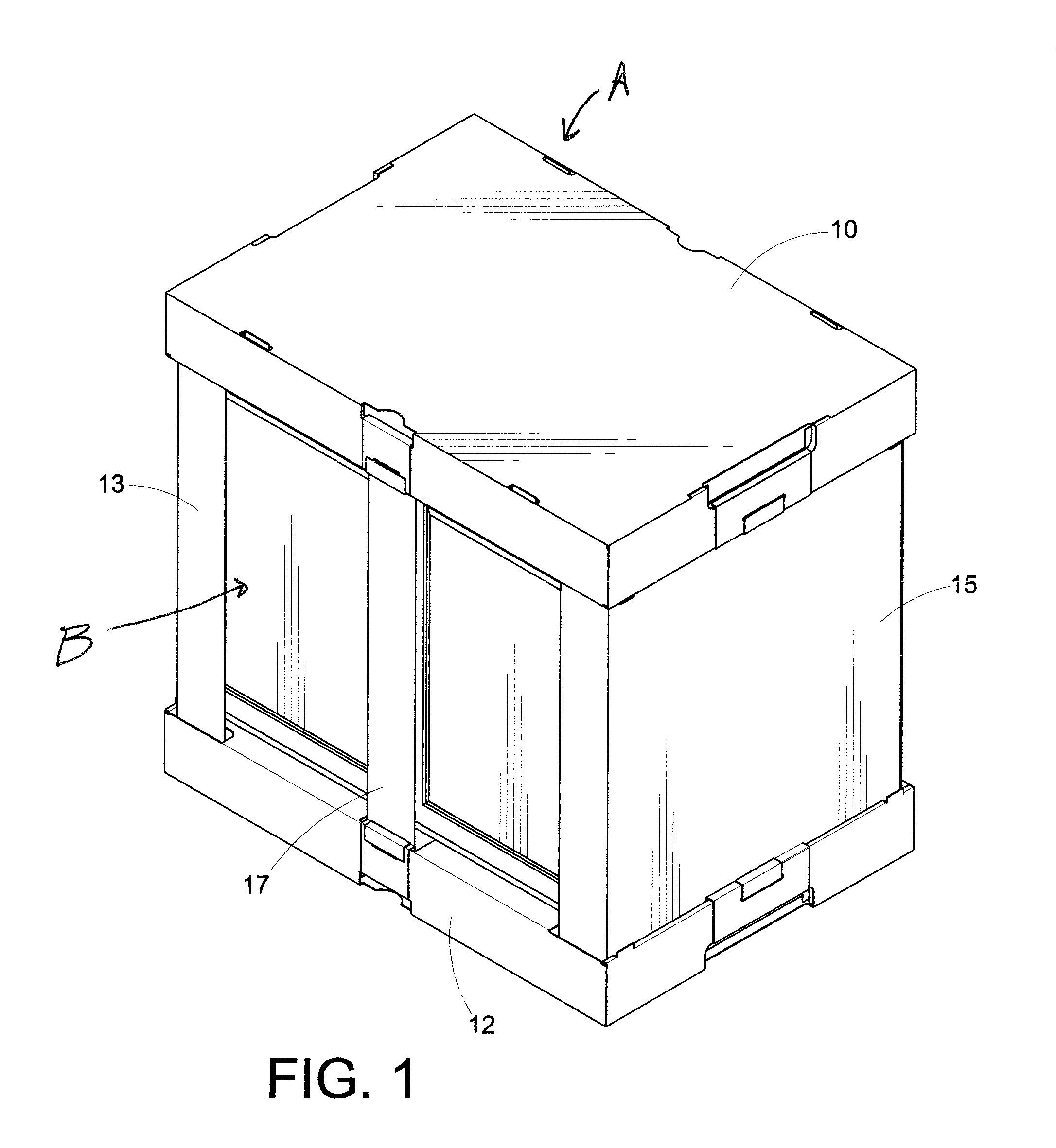
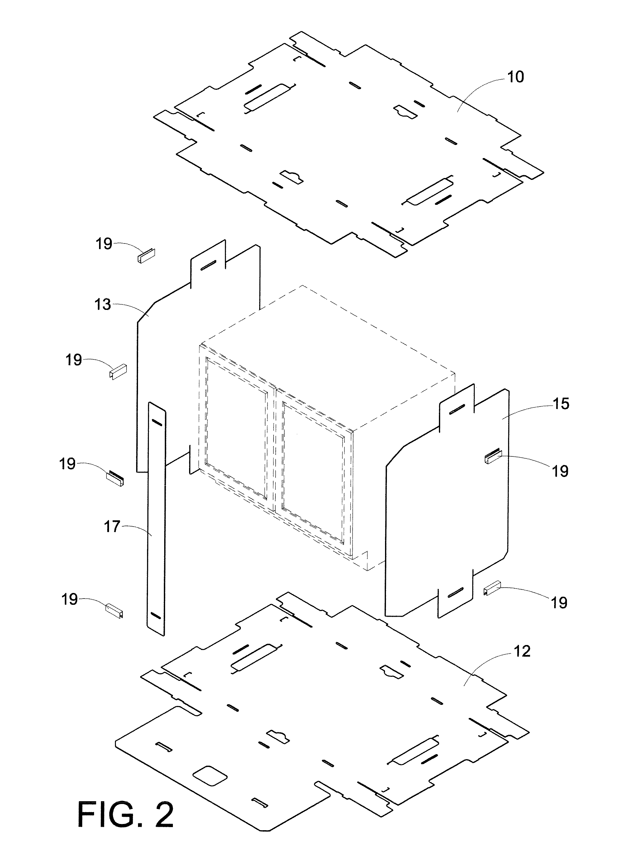
[0039]Referring now to the drawings wherein the showings are for purposes of illustrating one or more exemplary embodiments, FIGS. 1-24 illustrate a bandless packaging system or design A suitable for packaging an article, such as a cabinet B. The improved design allows a cabinet or other article to be shipped in an upper packaging member or cap 10 (shown in an unassembled or unfolded state in FIGS. 2 and 6) and a lower packaging member or base tray 12 (shown in an unassembled or unfolded state in FIGS. 2, 7 and 21-24) without using conventional bands or banding to hold the package together. A pair of shrouds 13, 15 extends between the cap and base tray. Further, at least one security strip 17 extends between the cap and base tray. Clips 19 are used to retain and secure the shrouds and strips in place with respect to the cap and base tray. Since clips are used, no adhesive or glue is required to secure and hold the assembly together.

[0040]Referring now to FIG. 6, cap 10 includes a ce...


PUM


Abstract

A bandless packaging assembly for cabinets includes a top packaging member including a front wall, a back wall and first and second side walls; a bottom packaging member including a front wall, back wall and first and second side walls; at least one side member extending between a first side wall of the top packaging member and a first side wall of the bottom packaging member; wherein the side member includes an upper flap and a lower flap which are received in corresponding slots formed in the top packaging member and the bottom packaging member; and at least one strip extending between front and back walls of the top packaging member and the bottom packaging member. The strip is received by slots formed in the front and back walls of the top packaging member and bottom packaging member.

Description

CLAIM OF PRIORITY[0001]This application claims priority from U.S. Provisional Application Ser. No. 61 / 143,469 filed on Jan. 9, 2009, which is hereby incorporated by reference.BACKGROUND OF THE DISCLOSURE[0002]The present disclosure generally relates a packaging design or system for packaging wooden or metal cabinets or other articles, and more particularly relates to a bandless cabinet packaging design.[0003]The disclosure relates to packages made of stiff, foldable packaging material, such as cardboard. The packages typically include two separate upper and lower boxes, which are each folded out of a single blank with a base wall, front wall, back wall, and side walls for each box. The front, back and side walls are formed of folding flaps which are joined to the base wall.[0004]This disclosure is concerned with the design of boxes which can package large articles such as cabinets. The package is divided, consisting as it does of two separable boxes joined to one another by shrouds,...

Claims


Application Information

Patent Timeline
IPC IPC(8): B65D85/64
CPCB65D85/64B65D5/22
Inventor DEJESUS, LOUIS
Owner THIRD DIMENSION
Learn More