Product display with improved pull-through frame arrangements

a product display and pull-through frame technology, applied in the field of product display with improved pull-through frame arrangement, can solve the problems of affecting the use of the product, the customer may just place the package in an improper location, and the product of this type is difficult to handle in the push-forward type display tray, so as to avoid potential losses and widen the use

Inactive Publication Date: 2010-07-15
TRION IND
View PDF18 Cites 115 Cited by
  • Summary
  • Abstract
  • Description
  • Claims
  • Application Information

AI Technical Summary

Benefits of technology

[0005]In accordance with one aspect of the invention, a new and improved form of product dispensing tray is provided, which is particularly useful for the display and dispensing of food and other products, packaged as described, with a pocket projecting forwardly from a flat and somewhat larger base element. In the improved tray of the invention, a supporting and dispensing frame element, accommodating the forward projection of a product pocket while restraining the base portion of the package, is positioned at a point spaced rearwardly of a front barrier element provided at the forwardmost extremity of the tray. The frame is spaced rearwardly a distance which corresponds to the forward projecting portion of a package received in the frame, plus at least the full thickness of one package. Accordingly, whenever a customer withdraws a product package through the frame and then has a change of mind about the product, the withdrawn product can be reinserted into the front of the display tray, in the space between the front barrier and the package which has just been advanced into the frame by reason of the pushing action of the tray. The returned package stands upright in the display, at the front thereof, and is in all respects available and ready for selection and extraction by a subsequent customer. A customer who has had a change of mind does not have to hunt for a place to lay down the unwanted product item, and the storekeeper avoids a potential losses resulting from defacing or damaging of the product resulting from the customer discarding it in an unsuitable location.
[0006]An additional and especially advantageous feature of the invention resides in the construction of a display tray of the type and having the features mentioned in the preceding paragraph, in which the supporting and dispensing frame and the desired positioning of the frame is accomplished by means of a novel and advantageous form of tray insert. The arrangement is such that the tray itself can be of multi-purpose design, suitable for handling of special packages with forwardly projecting pockets, and for other, more conventional package forms, such as typical boxes, bags, etc. The tray itself may be of a universal design, suitable for a wide variety of products. However, by placing an insert according to the invention in the front portion of the tray, it is automatically converted to a tray with a supporting and dispensing frame as described above and with the desired open spacing at the front to accommodate a dispensed but unwanted product. This is an important advantage to the storekeeper and manufacturer alike in enabling wider usage of a standardized (and therefore more economical) form of tray, which can be modified for special-purpose usage by installation of a removable insert.

Problems solved by technology

Products of this type tend to be difficult to handle in push forward type display trays.
One of the problems with known display trays of the type mentioned above is that, whenever a customer removes a package and then changes his or her mind (a not infrequent occurrence), dealing with the removed but unwanted package presents a problem.
In the end, the customer may just place the package in an improper location, wherever space can be found.
Another disadvantage of known display trays of the type described is that they tend to be single-purpose units.
In this respect, while suited for display and dispensing of the particular type of product described above, the conventional trays are largely or at least somewhat unsuitable for dispensing of other products.

Method used


Image

  • Product display with improved pull-through frame arrangements
  • Product display with improved pull-through frame arrangements
  • Product display with improved pull-through frame arrangements

Examples


Embodiment Construction

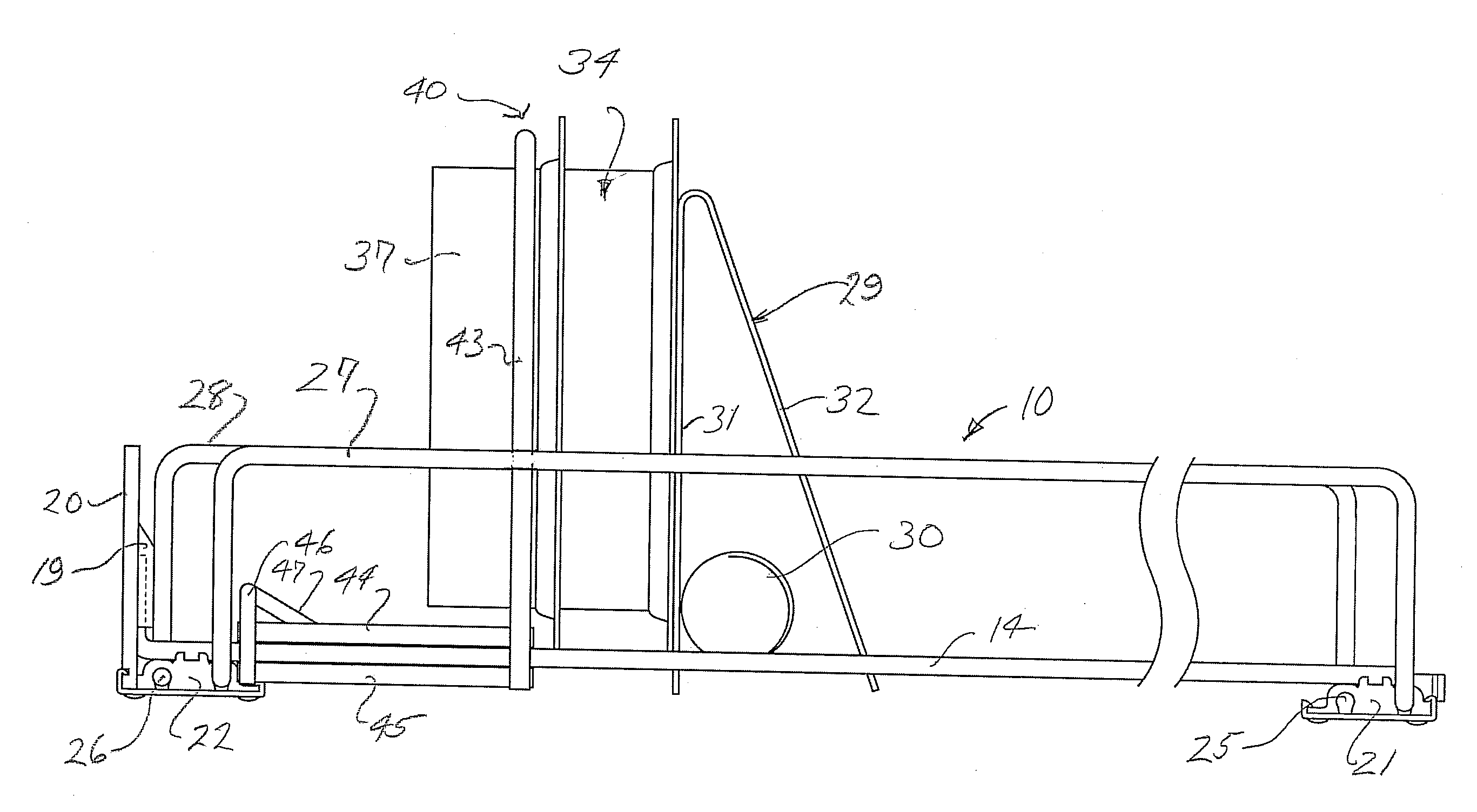
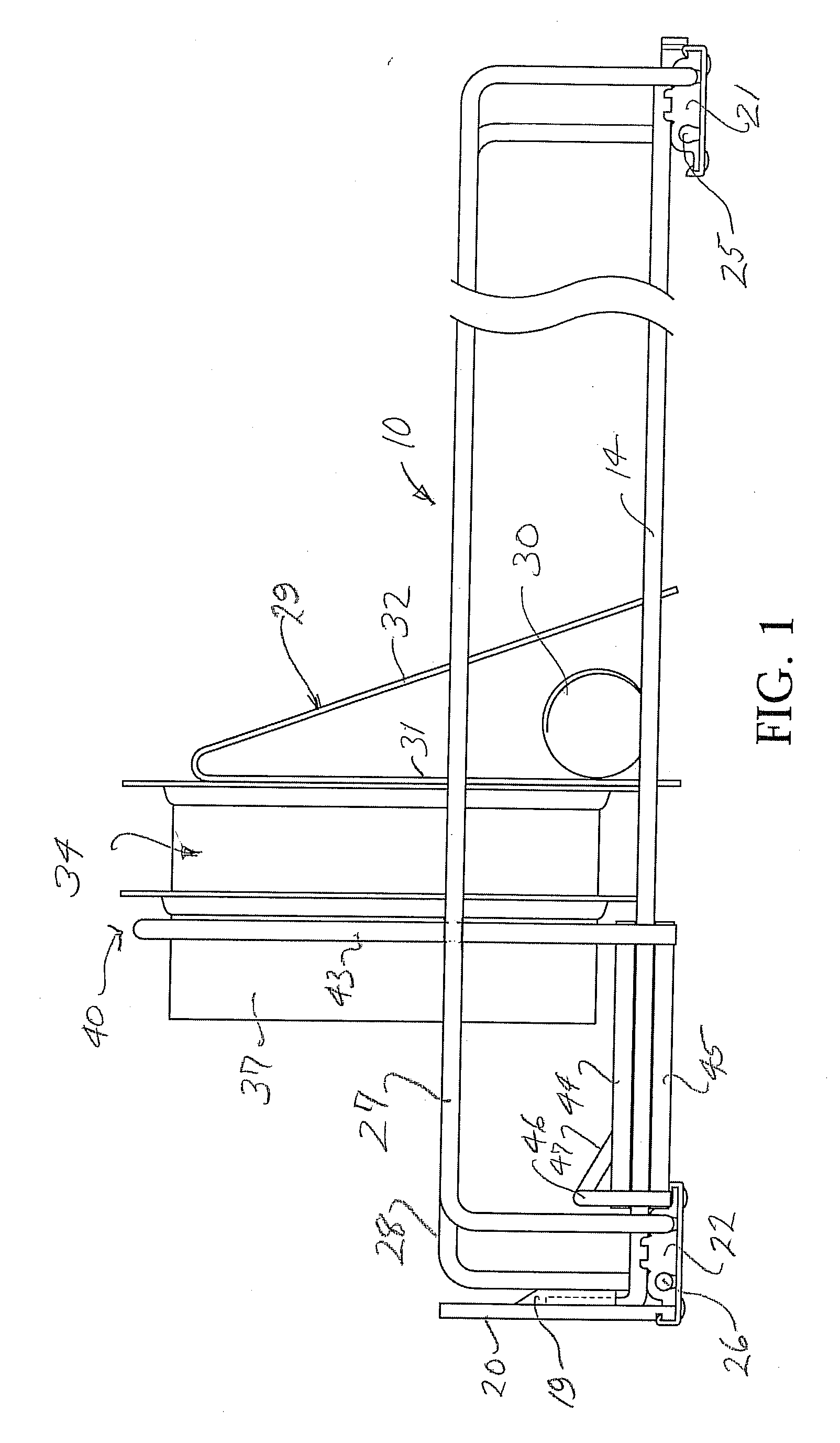
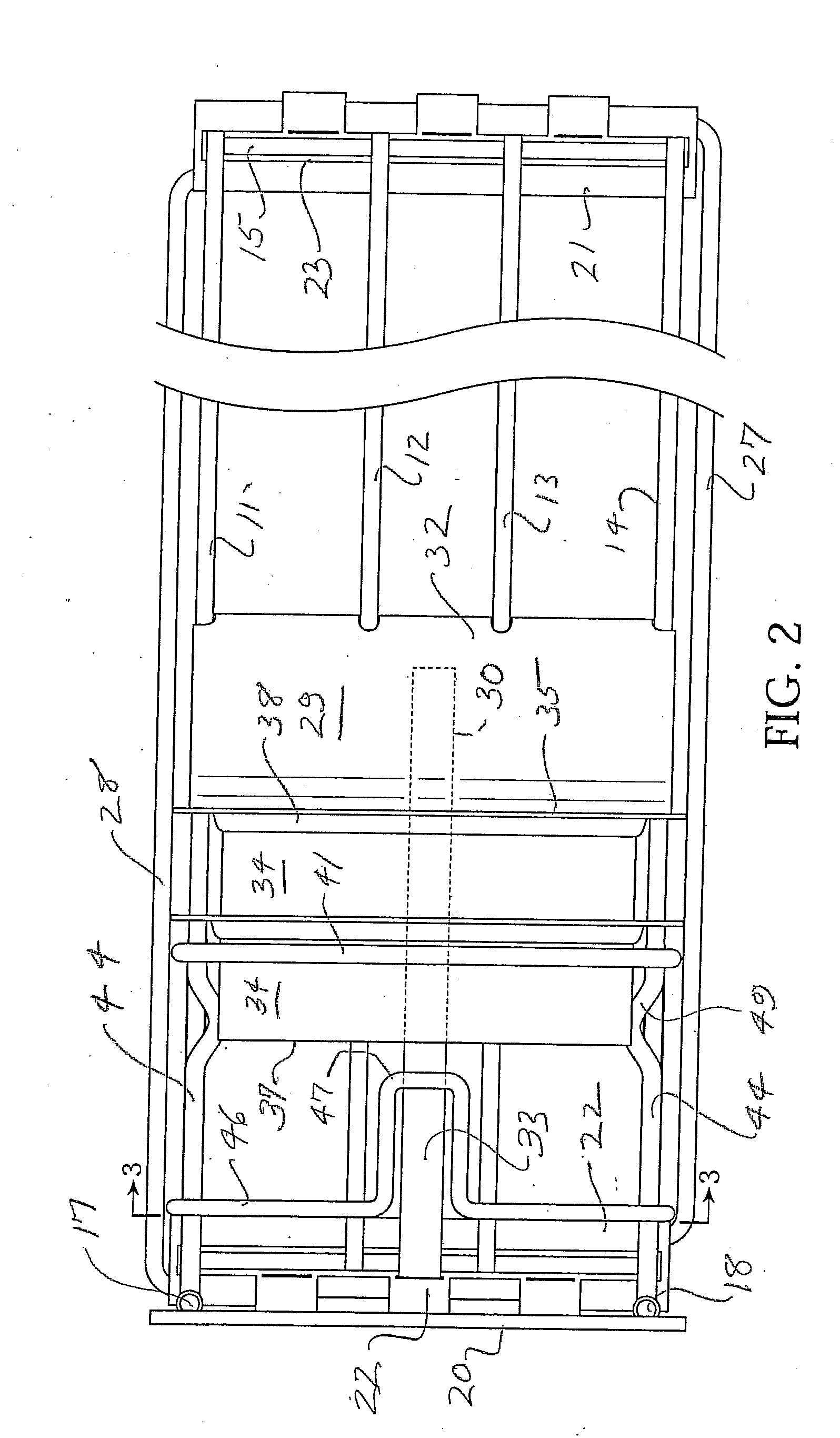
[0014]Referring now to the drawing, the reference numeral 10 designates generally a preferred form of product display tray in which the features of the invention are advantageously incorporated. Features of such display trays are shown in U.S. Pat. Nos. 6,745,906, 6,866,155, 6,866,700, 6,889,855 and 7,032,761, and the disclosures of these patents are incorporated herein by reference. In the illustrated form of tray, shown best in FIGS. 1 and 2, there is a base formed of four longitudinally extending wires 11-14. These longitudinally extending wires are joined at their back edges by a rear cross bar 15. At the forward end of the base there is a front cross bar 16 which is fixed to the forward ends of the two internal wires 12, 13 and is fixed to the outside wires 11, 14 adjacent the forwardmost end portions thereof. In the illustrated tray, the forward extremities 17, 18 of the outer wires 11, 14 are bent upwardly and are arranged to be received in opposite side sockets 19 of a front...


PUM


Abstract

A display tray for specially shaped packages (e.g., sliced meat products), having flat, flexible bases and a forwardly projecting housings for the product, typically, typically with recesses in the base to accommodate nesting. A vertical frame at the front, permitting the product housing to project through while normally retaining the base and while also allowing the base to be pulled through by a customer, is known. The new tray positions this frame a sufficient distance behind a front stop of the tray to enable a customer to replace a pulled-through product into the tray, in front of the frame and a product projecting through the frame. To particular advantage, the thus-positioned frame is incorporated into a special tray insert, easily installed in a general purpose tray to accommodate the described, specially shaped packages, and easily removed from the tray to render it more suitable for the display of general merchandise.

Description

BACKGROUND OF THE INVENTION [0001]In the store display of small product items, it is a common practice to provide display trays arranged to receive a plurality of product items in a front-to-back column, with a spring actuated pusher paddle at the back of the column arranged to automatically move the column forward each time a product item is removed from the front of the display. This makes for a more sales-attractive display, by keeping the merchandise always available at the front of the display where it is easily seen and easily removed.[0002]In the case of some products, such as packaged sandwich meats, for example, the product (e.g., a plurality of slices of sandwich meat) is received in a plastic pocket, typically of cylindrical shape, which is mounted on a rectangular base, also typically of plastic material, forming a sealed package. Products of this type tend to be difficult to handle in push forward type display trays. Accordingly, it is known to provide such trays with a...

Claims


Application Information

Patent Timeline
Patent Type & Authority Applications(United States)
IPC IPC(8): A47F1/04A47F7/00
CPCA47F1/126A47F1/04A47F5/01
Inventor NAGEL, THOMAS O.KOLOGE, JOSEPH F.
Owner TRION IND
Why Eureka
Try Eureka