Transformer, switching power supply device, and dc-dc converter device

a transformer and switching power supply technology, applied in the direction of transformer/inductance details, inductances with magnetic cores, inductances, etc., can solve the problems of increasing reducing the possibility of core breaking, and reducing the growl noise of transformers.

Inactive Publication Date: 2010-07-15
CANON KK
View PDF2 Cites 13 Cited by
  • Summary
  • Abstract
  • Description
  • Claims
  • Application Information

AI Technical Summary

Benefits of technology

[0020]In view of the above-mentioned problems, an object of the present invention is to reduce growl noise of ...

Problems solved by technology

This can lead to a situation where a driving frequency of a transformer included in the power supply device becomes an audible frequency.
Besides, ...

Method used


Image

  • Transformer, switching power supply device, and dc-dc converter device
  • Transformer, switching power supply device, and dc-dc converter device
  • Transformer, switching power supply device, and dc-dc converter device

Examples


first embodiment

[0037]A first embodiment is described below.

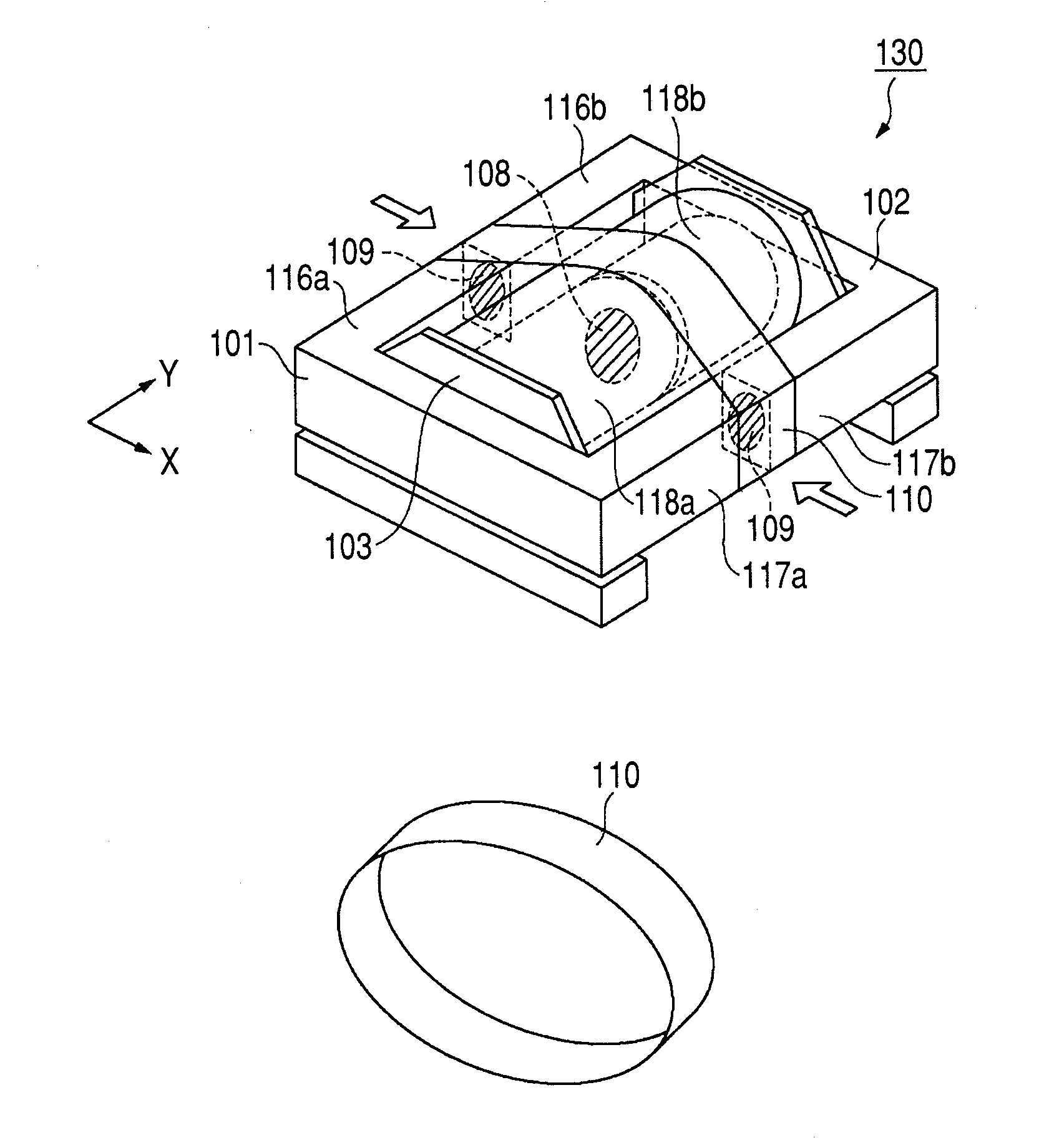
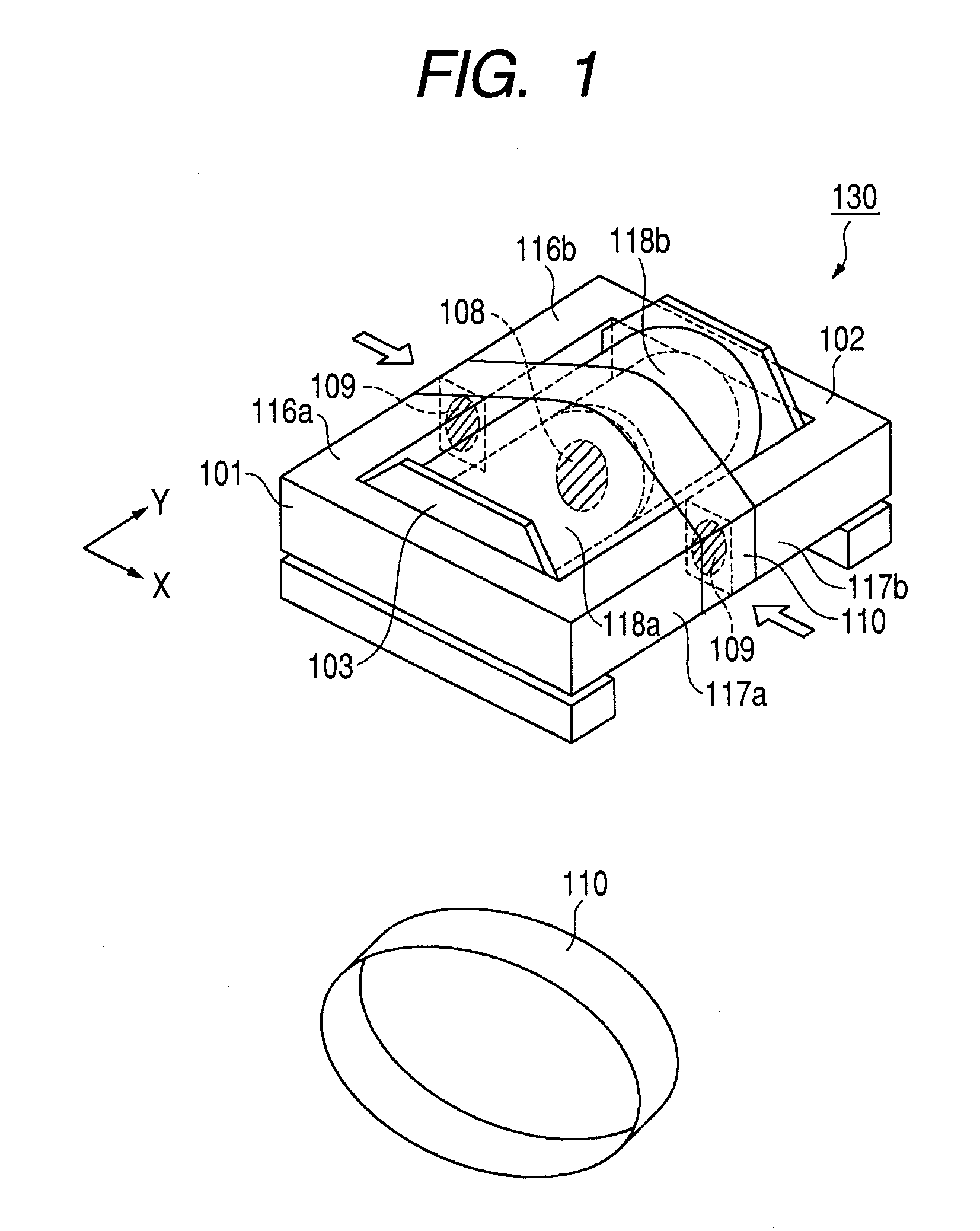
[0038]FIG. 1 is a perspective view illustrating an EE type transformer 130 according to the first embodiment.

[0039]For example, the transformer 130 is used in a switching power supply device, a DC-DC converter device, and the like. A first ferrite core 101 shaped like the letter E in horizontal section includes a first magnetic outer leg 116a, a second magnetic outer leg 117a, and a magnetic center leg 118a. Likewise, a second ferrite core 102 includes a first magnetic outer leg 116b, a second magnetic outer leg 117b, and a magnetic center leg 118b. The first ferrite core 101 is an example of a first core, and the second ferrite core 102 is an example of a second core.

[0040]A coil bobbin 103 has a primary coil and a secondary coil wound thereon. A shaft of the coil bobbin 103 is hollow, and the magnetic center legs 118a and 118b are inserted through this hollow shaft. A horizontal direction is a direction parallel to a horizontal plane tha...

second embodiment

[0056]The following describes a

[0057]In the first embodiment, the heat shrinkable tube 110 is used as the elastic member that applies pressure to the magnetic outer legs of the first ferrite core 101 and the magnetic outer legs of the second ferrite core 102. In the second embodiment, a flexible tube is used as the elastic member. The heat shrinkable tube 110 shrinks when heated. On the other hand, the flexible tube does not need such a heating step, and therefore the manufacturing process can be simplified.

[0058]FIG. 4 is a perspective view illustrating an EE type transformer 400 according to the second embodiment. A flexible tube 410 is adopted instead of the heat shrinkable tube 110. As the flexible tube 410, a tube made from a material having an excellent high temperature resistance, heat cycle resistance, tear resistance, and fire retardance, such as silicon rubber, can be used.

[0059]According to the second embodiment, the effect of simplifying the manufacturing process can be ...

third embodiment

[0060]The following describes a

[0061]As the elastic member that applies pressure to the magnetic outer legs of the first ferrite core 101 and the magnetic outer legs of the second ferrite core 102, the heat shrinkable tube 110 is adopted in the first embodiment and the flexible tube 410 is adopted in the second embodiment. In the third embodiment, a springing member is adopted.

[0062]FIG. 5 is a perspective view illustrating an EE type transformer 500 according to the third embodiment. In this embodiment, a springing member 510 is adopted instead of the heat shrinkable tube 110 or the flexible tube 410. The springing member 510 applies pressure to the magnetic outer legs of the first ferrite core 101 and the magnetic outer legs of the second ferrite core 102, in the direction from the magnetic outer legs toward the magnetic center legs. This enables an interfacial pressure to act upon the abutting surfaces of the magnetic outer legs.

[0063]According to the third embodiment, the same e...


PUM


Abstract

The transformer includes: first and second cores each including a magnetic center leg and a magnetic outer leg positioned outside of the magnetic center leg; a first adhesion part that adheres the magnetic center leg of the first core and the magnetic center leg of the second core to each other; a second adhesion part that adheres the magnetic outer leg of the first core and the magnetic outer leg of the second core to each other; a bobbin inserted through the magnetic center leg of the first core and the magnetic center leg of the second core, a primary coil and a secondary coil being wound on the bobbin; and an elastic member that applies pressure to the magnetic outer leg of the first core and the magnetic outer leg of the second core in a neighborhood of the second adhesion part, in an inward direction of the transformer.

Description

BACKGROUND OF THE INVENTION[0001]1. Field Of The Invention[0002]The present invention generally relates to a transformer, and more particularly relates to a transformer that is used in a switching power supply device or a DC-DC converter device.[0003]2. Description Of The Related Art[0004]A transformer is a main electronic component used in a switching power supply device or a DC-DC converter device. The transformer is also called a voltage converter or an electric transformer. In the transformer, a magnetic field is created by a primary coil, and the magnetic field is transferred to a secondary coil coupled with the primary coil by a mutual inductance, thereby inducing a current in the secondary coil. This allows an input voltage to be stepped up or stepped down.[0005]FIG. 6 is a perspective view illustrating a typical EE type transformer 100. A first ferrite core 101 and a second ferrite core 102 shaped like the letter E in horizontal section each have a magnetic center leg at the...

Claims


Application Information

Patent Timeline
IPC IPC(8): H01F27/28
CPCH01F3/14H01F27/33H01F27/263
Inventor HAYASAKI, MINORUSAMEJIMA, KEISUKE
Owner CANON KK
Why Eureka
Try Eureka