Image sensor driving apparatus

a driving apparatus and image sensor technology, applied in the direction of color television, television system scanning details, television systems, etc., can solve the problems of increasing achieve the reduction of so as to reduce the fabrication cost. , the effect of reducing the number of developing processes

Inactive Publication Date: 2010-07-15
PANASONIC CORP
View PDF5 Cites 15 Cited by
  • Summary
  • Abstract
  • Description
  • Claims
  • Application Information

AI Technical Summary

Benefits of technology

[0030]The image sensor driving apparatus according to the present invention is provided with a plurality of dual-purpose binary / ternary output blocks having the functions of both a binary output block and a ternary output block, in such a way as to change over between binary output and ternary output through driving / controlling signals from the timing generator, and in such a way as to adjust the ON resistances of the output transistors by controlling the output transistors, which enables optimization of the characteristics of the output blocks according to the device to which the respective output levels are supplied. As a result, with the present invention, it is possible to eliminate the necessity of developing individual vertical drivers adaptable to various types of image sensors, thereby largely reducing the number of developing processes and the fabrication cost. Accordingly, with the image sensor driving apparatus according to the present invention, it is possible to change over between the functions of the binary and ternary output blocks which output respective voltage levels which have been preliminarily included in an LSI circuit (Large-scale Integrated circuit) for a single vertical driver, which can eliminate the necessity of designing an additional LSI for coping with the difference in the image-sensor driving mechanism, thereby reducing the number of developing processes and the fabrication cost.

Problems solved by technology

Accordingly, there has been a need for designing the vertical driver according to the specifications of each image sensor, thereby increasing the number of developing processes and the fabrication cost.

Method used


Image

  • Image sensor driving apparatus
  • Image sensor driving apparatus
  • Image sensor driving apparatus

Examples


first embodiment

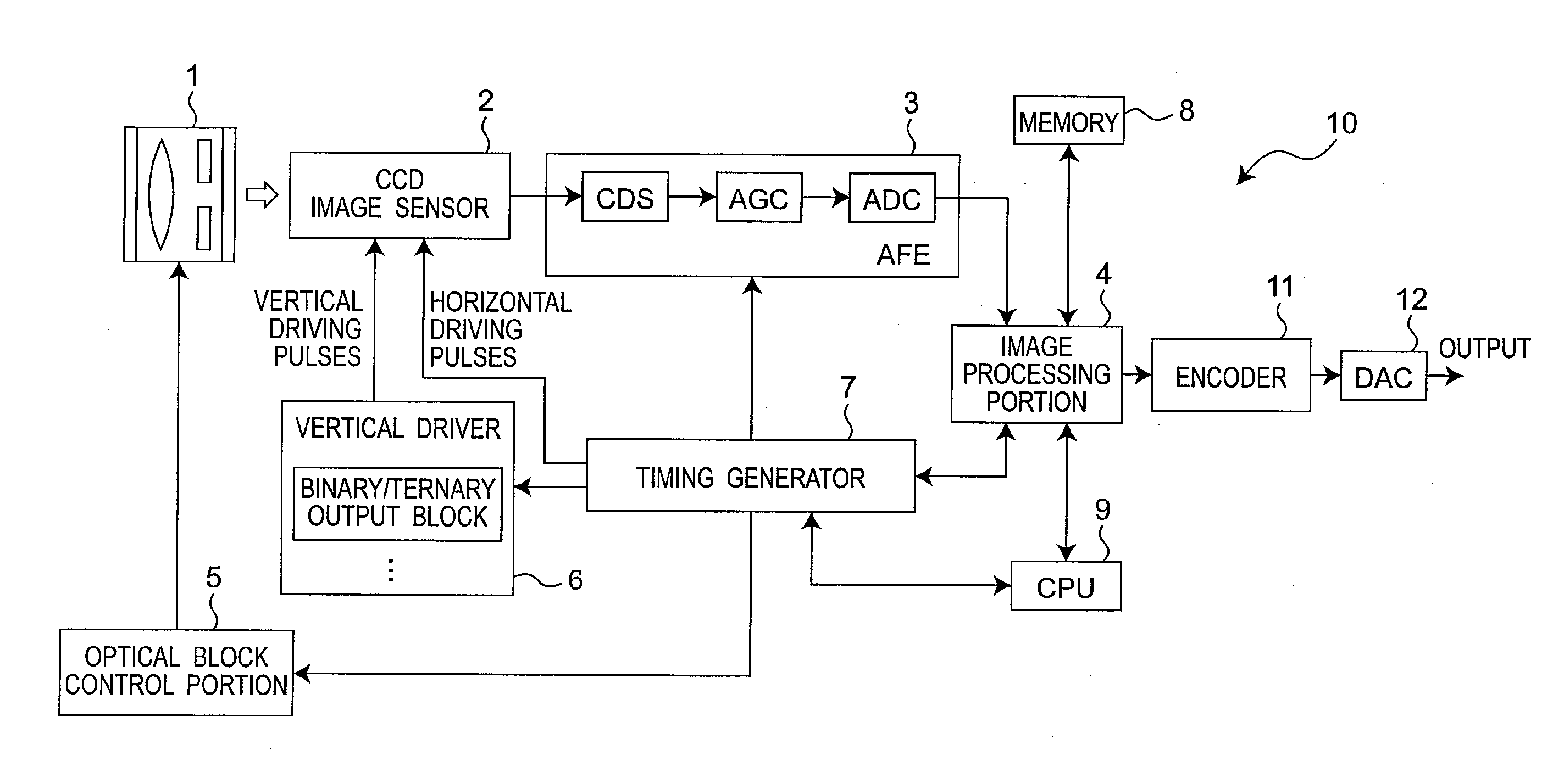
[0059]FIG. 1 is a block diagram illustrating the schematic structure of an image pickup apparatus using an image sensor driving apparatus according to a first embodiment of the present invention. The image pickup apparatus according to the first embodiment will be described, by exemplifying a digital still camera. As illustrated in FIG. 1, the image pickup apparatus 10 is provided with an optical block 1 having optical instruments such as a lens, a diaphragm mechanism and a shutter mechanism, a CCD image sensor 2 which receives light from the optical block 1 and converts it into electrical signals, an AFE (Analog Front-End) 3 which digitalizes electrical signals from the CCD image sensor 2, an image processing portion 4 which receives digital signals inputted thereto from the AFE 3, then performs image processing thereon and outputs image signals, an optical-block control portion 5 which controls the diaphragm mechanism, the shutter mechanism and the like in the optical block 1, a v...

second embodiment

[0081]Hereinafter, with reference to FIG. 4, a second embodiment of the present invention will be described, with respect to an image pickup apparatus using an image sensor driving apparatus which is a semiconductor integrated device.

[0082]FIG. 4 is a block diagram illustrating the structure of a single dual-purpose binary / ternary output block in a vertical driver 60 in the image pickup apparatus according to the second embodiment of the present invention. In the image pickup apparatus according to the second embodiment, the structures of the other portions than the vertical driver 60 are the same as those of the image pickup apparatus according to the first embodiment illustrated in FIG. 1. In the second embodiment, the components having the same functions and structures as those of the components of the image pickup apparatus according to the aforementioned first embodiment will be designated by the same reference characters, and the description of the first embodiment will be app...

third embodiment

[0096]Hereinafter, with reference to FIG. 5, a third embodiment of the present invention will be described, with respect to an image pickup apparatus using an image sensor driving apparatus which is a semiconductor integrated device.

[0097]FIG. 5 is a block diagram illustrating the structures of a vertical driver 70 and peripheral devices therefor, in the image pickup apparatus according to the third embodiment of the present invention. As illustrated in FIG. 5, the vertical driver 70 is provided with a plurality of dual-purpose binary / ternary output blocks, according to the specifications of the CCD image sensor 2. In the image pickup apparatus according to the third embodiment, the structures of the other portions than the vertical driver 70 are the same as those of the image pickup apparatus according to the first embodiment illustrated in FIG. 1. In the image pickup apparatus according to the third embodiment, the components having the same functions and structures as those of th...


PUM


Abstract

An image sensor driving apparatus is provided with a plurality of output blocks having the functions of both a binary output block and a ternary output block and, therefore, is adaptable to image sensors with various types of specifications. The image sensor is provided with a plurality of dual-purpose binary / ternary output blocks having the functions of both a binary output block and a ternary output block and is configured to change over between binary operations and ternary operations, according to driving / controlling signals from a timing generator or selection signals from the outside of the apparatus.

Description

[0001]THIS APPLICATION IS A U.S. NATIONAL PHASE APPLICATION OF PCT INTERNATIONAL APPLICATION PCT / JP2007 / 065174.TECHNICAL FIELD[0002]The present invention relates to an image sensor driving apparatus for driving an image sensor and, more particularly, relates to an image sensor driving apparatus for driving vertical registers in an image sensor.BACKGROUND ART[0003]FIG. 12 is a block diagram illustrating the schematic structure of a common image pickup apparatus having a CCD image sensor, such as an image pickup apparatus 100 used in a digital still camera. As illustrated in FIG. 12, the image pickup apparatus 100 is provided with an optical block 101 having optical instruments such as a lens, a diaphragm mechanism and a shutter mechanism, a CCD image sensor 102 which receives light from the optical block 101 and converts it into electrical signals, an AFE (Analog Front-End) 103 which digitalizes electrical signals from the CCD image sensor 102, an image processing portion 104 which r...

Claims


Application Information

Patent Timeline
Patent Type & Authority Applications(United States)
IPC IPC(8): H04N5/335H04N5/341H04N5/372H04N5/3728
CPCH01L27/14831H04N3/1537H04N5/3728H04N5/341H04N5/37213H04N3/155H04N25/40H04N25/709H04N25/713H04N25/73H04N25/745
Inventor HIMENO, AKIHISATANAKA, AKIRA
Owner PANASONIC CORP
Why Eureka
Try Eureka