Illumination system, collimator and spotlight

a technology of collimator and spotlight, which is applied in the field of illumination system, can solve the problems of unsatisfactory color-uniformity of light emitted by the known illumination system, and achieve the effect of increasing the efficiency of the system

Inactive Publication Date: 2010-07-15
KONINKLIJKE PHILIPS ELECTRONICS NV
View PDF11 Cites 12 Cited by
  • Summary
  • Abstract
  • Description
  • Claims
  • Application Information

AI Technical Summary

Benefits of technology

[0021]In an embodiment of the illumination system, a central wavelength of the light emitted by light emitting diode is within a range between 400 nanometers and 490 nanometers. Light having a central wavelength in a range between 400 and 490 nanometers is also known as blue light. A benefit of using blue light as the light of the first predefined color is that this light is visible to humans and thus can directly be mixed into the output of the color-tunable illumination system without conversion. Any conversion using luminescent materials to convert light from one color to another introduces some loss of energy due to a Stokes-shift involved in the conversion. By using blue light as the light of the first predetermined color, some of the light emitted by the color-tunable illumination system does not need to be converted, which increases the efficiency of the system.

Problems solved by technology

A drawback when using the phosphor-enhanced light emitting diode in the known illumination system is that the color-uniformity of the light emitted by the known illumination system is not optimal.

Method used


Image

  • Illumination system, collimator and spotlight
  • Illumination system, collimator and spotlight
  • Illumination system, collimator and spotlight

Examples


Embodiment Construction

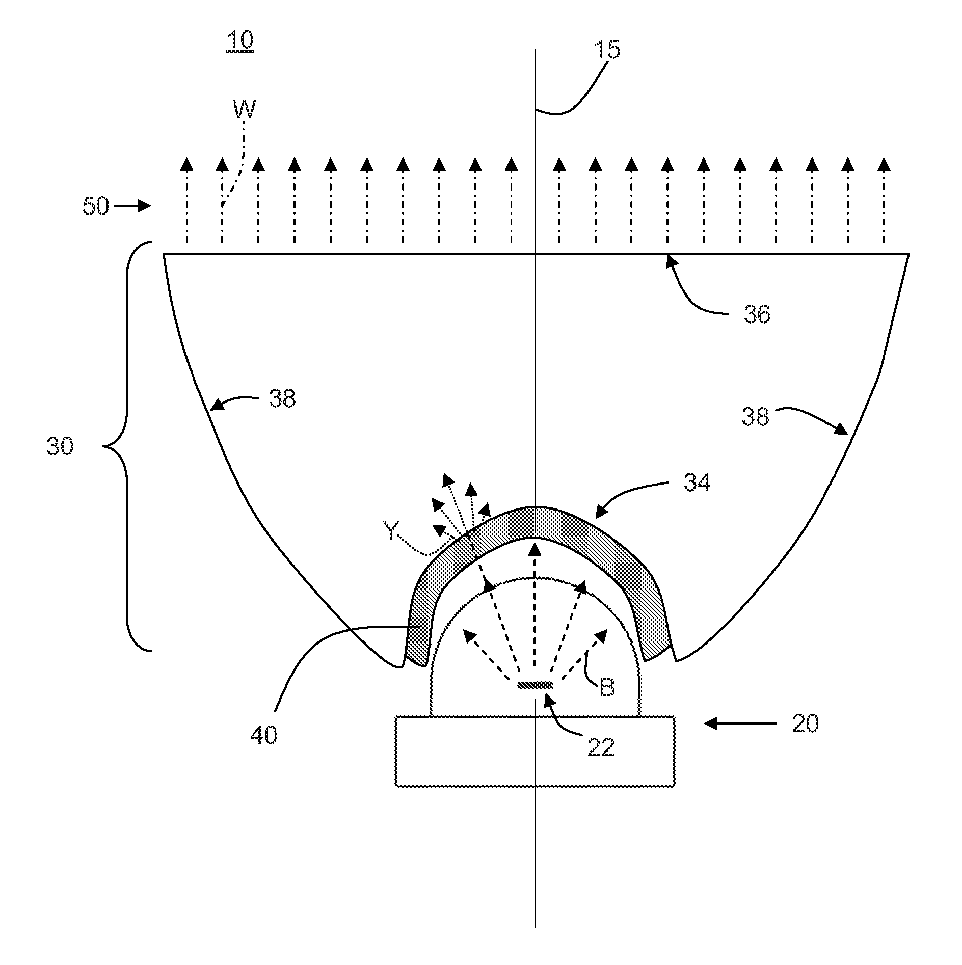
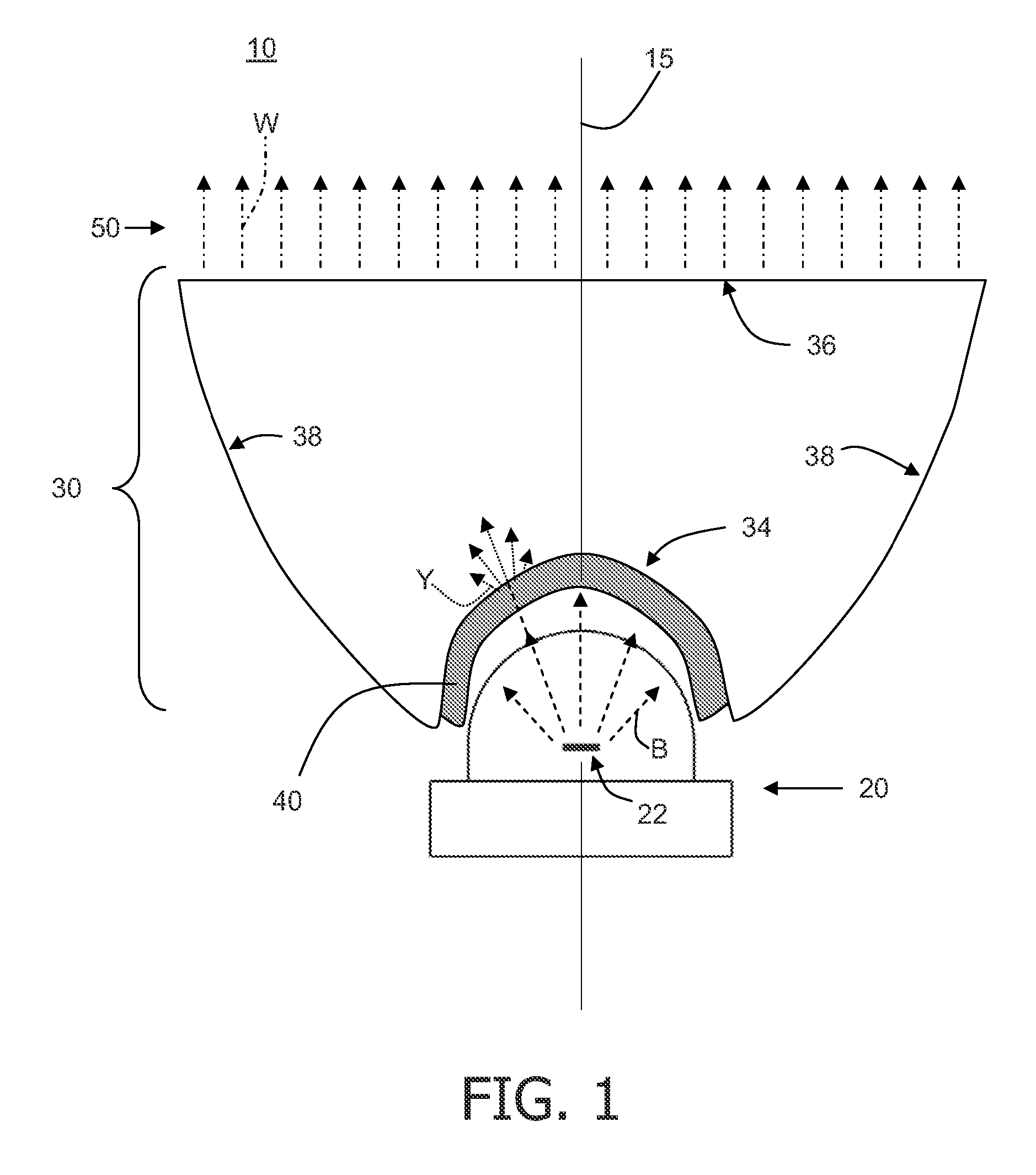
[0028]FIG. 1 shows a schematic cross-sectional view of an illumination system 10 according to the invention. The cross-sectional view shown in FIG. 1 is generated by intersecting the illumination system 10 with an imaginary plane (not shown) arranged parallel to the longitudinal axis 15. The illumination system 10 according to the invention comprises a light emitting diode 20, a collimator 30 and a luminescent layer 40. The light emitting diode 20 comprises a die 22 which emits light B via the luminescent layer 40 and the collimator 30 in a direction away from the illumination system 10. The luminescent layer 40 comprises a luminescent material which converts at least a part of the light emitted by the light emitting diode 20 into light of a predefined color Y. The collimator 30 is arranged for collimating the light B emitted by the light emitting diode 20 as well as the light Y to generate a beam of light 50 which is subsequently emitted from the illumination system 10. The collima...


PUM


Abstract

The invention relates to an illumination system (10, 12), a collimator (30, 32) for use in the illumination system and a spotlight. The illumination system comprises a light emitting diode (20), a collimator and a luminescent layer (40). The light emitting diode emits light via the luminescent layer and the collimator in a direction away from the illumination system. The collimator comprises a light input window (34) for receiving light from the light 5 emitting diode. The collimator further comprises a light exit window (36) for emitting a collimated beam of light. The light substantially progresses through the collimator via total internal reflection. The luminescent layer comprises luminescent material which converts at least part of the light emitted by the light emitting diode into light of a predefined color. The luminescent layer is applied to the light input window of the collimator.10 The effect of the measures according to the invention is that the application of the luminescent layer on the light input window of the collimator results in improved color uniformity and enables a remote phosphor arrangement while maintaining a collimated beam.

Description

FIELD OF THE INVENTION[0001]The invention relates to an illumination system comprising a light emitting diode, a collimator and a luminescent layer.[0002]The invention also relates to a collimator for use in the illumination system, and to a spotlight comprising the illumination system.BACKGROUND OF THE INVENTION[0003]Such illumination systems are known per se. They are used, inter alia, in spotlights. A spotlight is a lamp that produces a collimated beam of light to illuminate a restricted area. The spotlight may be used for general lighting purposes, for example, for office lighting, or for shop lighting, or for in-home general lighting purposes, or for theater lighting for illuminating part of the stage.[0004]Light emitting diodes are increasingly being used in illumination systems for general lighting purposes. The reason is that the efficiency and life-time of the light emitting diodes is relatively high, while the cost of the light emitting diodes is relatively low. Furthermor...

Claims


Application Information

Patent Timeline
Patent Type & Authority Applications(United States)
IPC IPC(8): F21V9/16F21K99/00F21V9/40
CPCF21K9/00F21V5/04F21V7/0091G02B19/0061G02B27/30G02B19/0028G02B17/086F21K9/64F21V9/30
Inventor VAN OERS, DENIS JOSEPH CARELWAUMANS, LARS RENE CHRISTIAN
Owner KONINKLIJKE PHILIPS ELECTRONICS NV
Why Eureka
Try Eureka