
Motion estimation technique for digital video encoding applications

a motion estimation and video encoding technology, applied in the field of digital video encoding techniques, can solve the problems of affecting the quality of motion estimation search process,

Inactive Publication Date: 2010-07-15
SASKEN COMMUNICATION TECHNOLOGIES
View PDF16 Cites 51 Cited by
  • Summary
  • Abstract
  • Description
  • Claims
  • Application Information

AI Technical Summary

Benefits of technology

Enhances encoder performance by improving motion estimation efficiency without compromising compression quality and reducing search time, allowing for real-time implementation at a reasonable cost.

Problems solved by technology

Since a single frame of video can consist of thousands or even hundreds of thousands of bits of information, it can take a considerable amount of time to transmit a sequence of frames from one point to another.
Although this method can produce the best motion vector according to predetermined matching criterion, it is usually too complex to implement for real-time applications at a reasonable cost.
The problem with this approach is the selection of a reasonable fixed pre-defined threshold for stopping criteria during a local search for all macroblocks.
If the selected predefined threshold is relatively high, the motion estimation search process can stop prematurely, selecting a non-optimal motion vector.
This can lead to lower quality for Constant Bit Rate (CBR) encoding or it can result in a lower compression ratio for the Variable Bit Rate (VBR), if the selected pre-defined threshold value is relatively low.
The local search process may not be able to satisfy the stopping criteria through an optimal or near optimal motion vector.
Therefore, choosing a fixed threshold can affect the quality of compression and encoder performance.

Method used


Image

  • Motion estimation technique for digital video encoding applications
  • Motion estimation technique for digital video encoding applications
  • Motion estimation technique for digital video encoding applications

Examples


Embodiment Construction

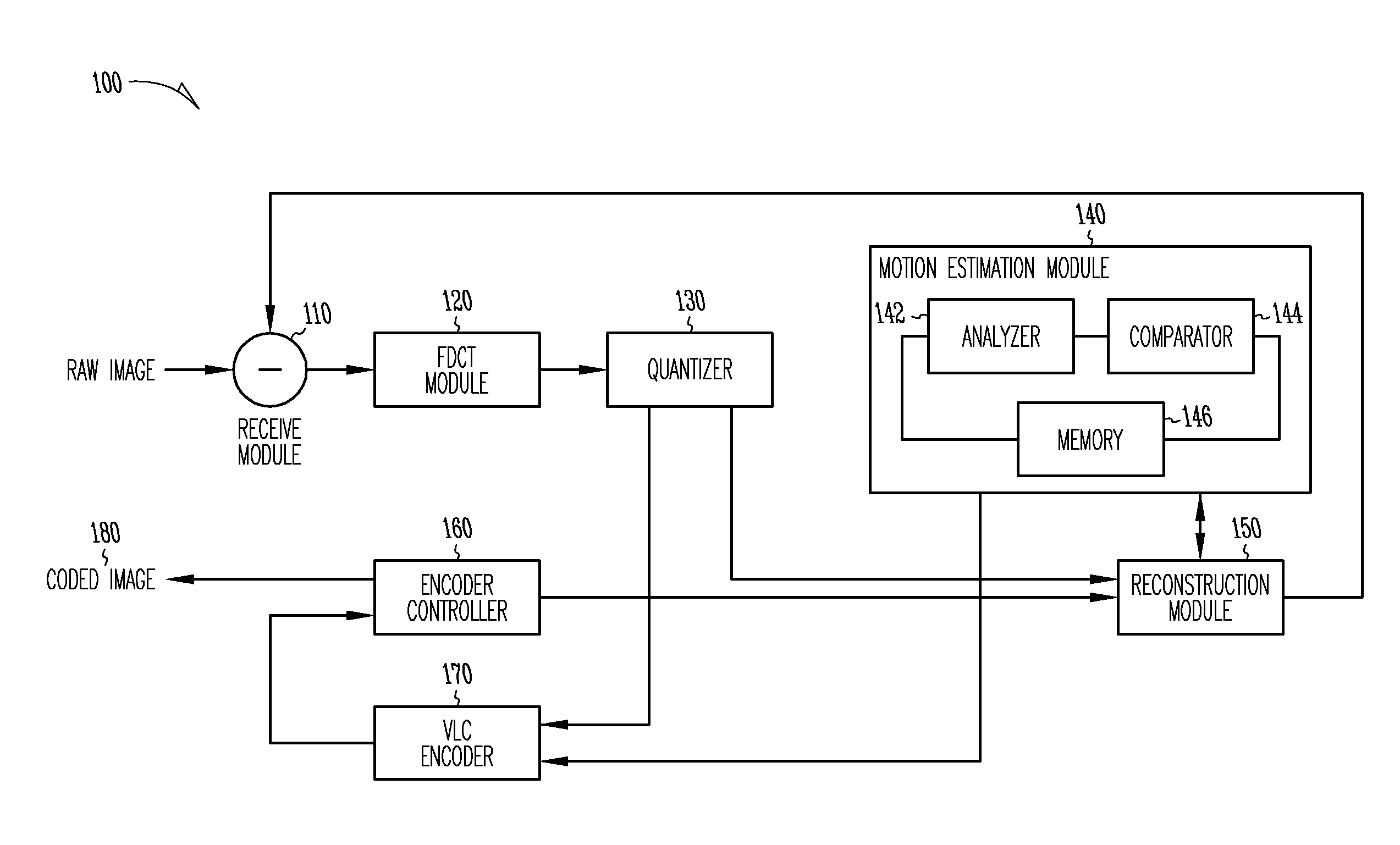
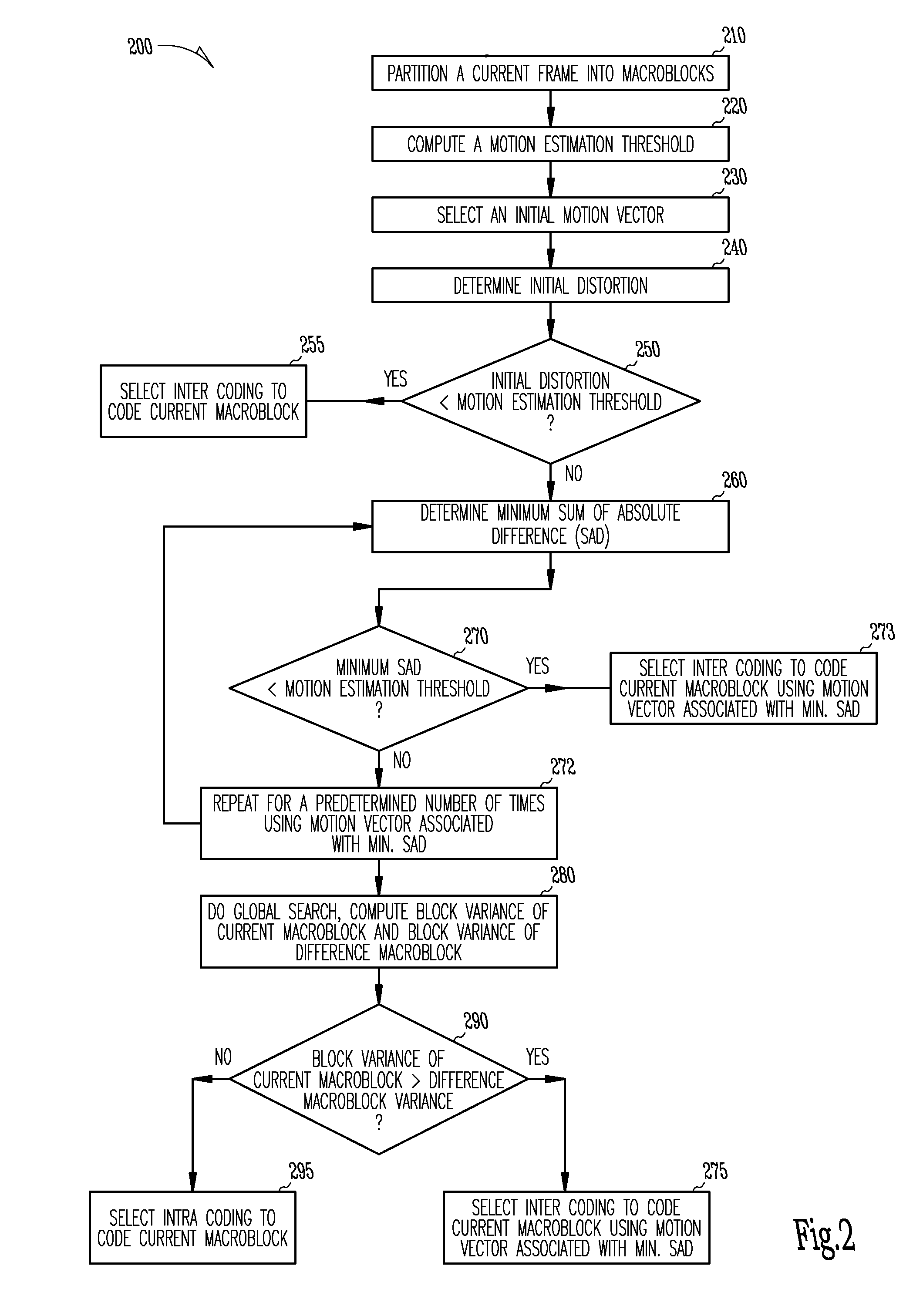
[0017]The present invention provides an efficient digital video compression technique that enhances encoder performance without compromising the quality of the compression during motion estimation. Also, the technique enhances encoder performance without increasing the search time for a motion vector. In one embodiment, this is accomplished by providing a computationally efficient processing technique to compute a frame-to-frame macroblock based motion vectors of digital images. The improved encoder receives a raw image in the form of a current frame. The encoder then performs an initial local search around an initial motion vector candidate derived from spatio-temporal neighboring macroblock parameters. The encoder then compares the user-defined complexity scalable sum of absolute difference between the original and the associated reference macroblock against an adaptive threshold value for motion estimation convergence. If the initial local search fails, the encoder then introduce...


PUM


Abstract

The present invention provides an improved motion estimation encoder for digital video encoding applications. In one example embodiment, the improved encoder receives a raw image in the form of a current frame and estimates the macroblock motion vector with respect to a reference frame. The encoder then performs an initial local search around an initial motion vector candidate derived from spatio-temporal neighboring macroblock parameters. The encoder then compares the user-defined complexity scalable sum of absolute difference between the original and the associated reference macroblock against an adaptive threshold value for motion estimation convergence. The encoder introduces a global full search around a candidate from a coarser level, in case an initial local search fails. The encoder then selects an inter encoding mode for coding the current macroblock, when the first local search is successful, otherwise the encoder selects the inter or intra encoding mode for encoding the current macroblock by comparing variances of the original and difference macroblocks.

Description

PRIORITY INFORMATION[0001]This application is a Divisional of U.S. application Ser. No. 10 / 202,236, filed on Jul. 24, 2002, which claims priority to U.S. Provisional Application No. 60 / 307,539, filed on Jul. 24, 2001, which applications are incorporated herein by reference in their entirety.FIELD OF THE INVENTION[0002]This invention generally relates to digital video encoding techniques, and more particularly to motion estimation techniques for digital video encoding applications.BACKGROUND[0003]In recent years, it has become increasingly desirable and practical to communicate digital video information—sequence of digital images—from one point to another. Indeed, transmission of video over computer networks, such as the World-Wide-Web portion of the Internet, from one computer to another is uncommon in digital television set-top boxes, DSS, HDTV decoders, DVD Players, Video Conferencing, Internet Video and other such applications. Since a single frame of video can consist of thousan...

Claims


Application Information

Patent Timeline
Patent Type & Authority Applications(United States)
IPC IPC(8): H04N7/32H04N5/14H04N7/26
CPCH04N5/145H04N19/56H04N19/00587H04N19/533H04N19/51
Inventor BHAUMIK, SANDIPMANOHOR, MURALIMANOJ, K. N.M. H., PRAKASH
Owner SASKEN COMMUNICATION TECHNOLOGIES
Learn More