Signal method and apparatus

a technology of orthogonal frequency division and signal, applied in the field of signal methods and apparatuses, can solve the problems of meliorating technical and economic problems, and achieve the effect of reducing the number of optical channel generators used

Active Publication Date: 2010-07-15
MONASH UNIV
View PDF13 Cites 185 Cited by
  • Summary
  • Abstract
  • Description
  • Claims
  • Application Information

AI Technical Summary

Benefits of technology

[0018]Some embodiments have the advantage of generating an optical channel from a plurality of data streams, which reduces the number of optical

Problems solved by technology

Advantageously, in at least one embodiment, electronics such as DACs and ADCs having a bandwidth comparable with the bands rather than the bandwidth of the signal can be used

Method used


Image

  • Signal method and apparatus
  • Signal method and apparatus
  • Signal method and apparatus

Examples


Embodiment Construction

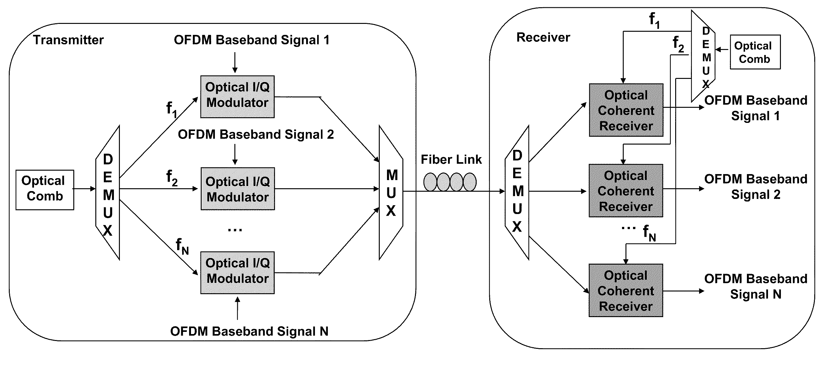
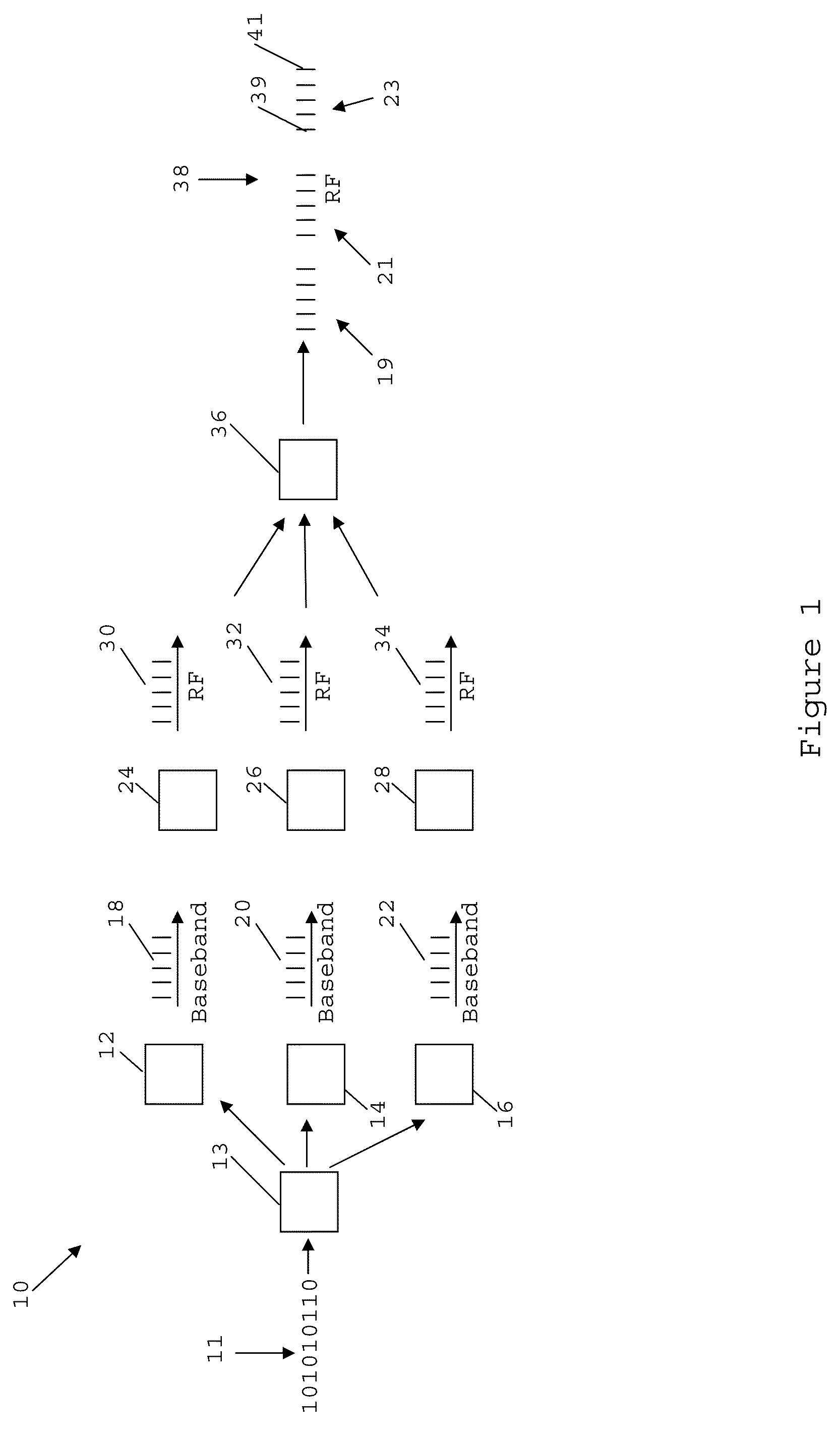
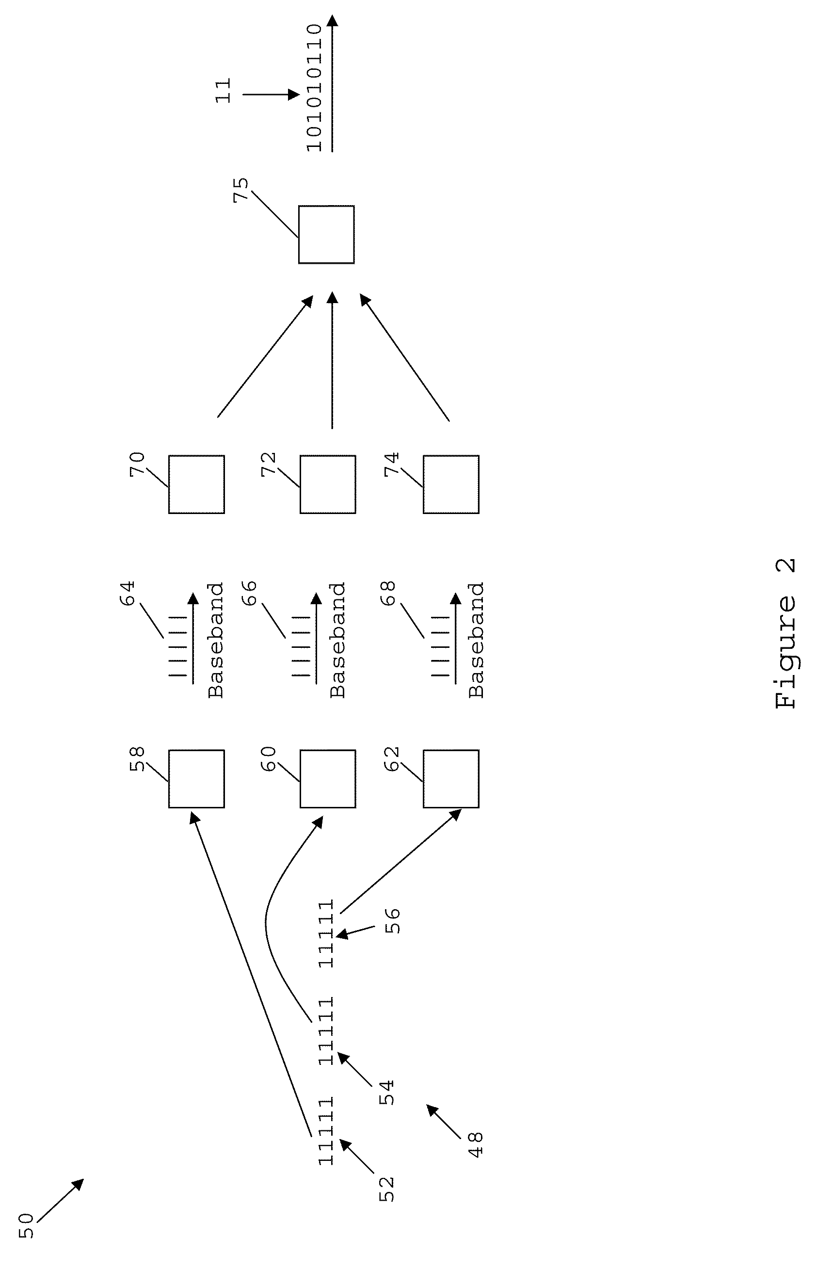
[0107]In one embodiment a signal comprising a plurality of mutually orthogonal subcarriers constituting a plurality of bands is generated, transmitted, and then processed at a receiver. Each band is generated separately using relatively slow electronics and then the bands are combined to form a fast signal. As a result, the electronics and especially DAC / ADCs in the apparatus do not need to operate at an extremely high sampling rate. The DAC / ADCs only require a bandwidth approximately equal to each OFDM band, which is approximately the signals original bandwidth divided by the number bands. When the signal is an OFDM signal, dividing the OFDM spectrum into multiple orthogonal bands is called by the applicant ‘orthogonal-band-multiplexed OFDM’ (OBM-OFDM). The OFDM bands can be multiplexed and de-multiplexed without inter-band interference because they are orthogonal.

[0108]The subcarriers are mutually orthogonal provided, for example, that they are spaced apart in frequency by an inte...


PUM


Abstract

Methods and apparatus for generating and processing a signal are disclosed. The signal may comprise a plurality of mutually orthogonal subcarriers constituting a plurality of bands. The signal may be either an optical or a radio frequency signal.

Description

FIELD OF THE INVENTION[0001]The present invention generally relates to the generation, transmission and detection of orthogonal frequency division multiplexed signals, and particularly but not exclusively to optical orthogonal frequency division multiplexed signals having orthogonal bands.BACKGROUND OF THE INVENTION[0002]Optical Frequency Division Multiplexing (OFDM) is a radio frequency format described, for example, by S. Hara and R. Prasad in Multicarrier Techniques for 4G Mobile Communications (Artech House, Boston, 2003). Any two subcarriers are orthogonal provided the difference in their frequency is given by m / Ts where m is an integer and Ts is symbol period. The symbol rate is the inverse of the symbol period. That is, the orthogonal subcarrier sets can be recovered with a correlator matched to the subcarrier without inter-carrier interference, in spite of strong signal spectral overlap. Radio frequency OFDM signals have some desirable properties including tolerance to dispe...

Claims


Application Information

Patent Timeline
IPC IPC(8): H04J14/02H04L27/00
CPCH04L25/0224H04L25/0242H04L27/2653H04L27/2637H04L27/264H04L27/2697H04L27/26414H04L27/26538
Inventor SHIEH, WILLIAM
Owner MONASH UNIV
Why Eureka
Try Eureka