Optical device and optical transmitter

Active Publication Date: 2010-07-15
FUJITSU LTD
View PDF8 Cites 0 Cited by
  • Summary
  • Abstract
  • Description
  • Claims
  • Application Information

AI Technical Summary

Benefits of technology

[0013]These together with other aspects and advantages which will be subsequently apparent, reside in the details of construction and operation as more fully h

Problems solved by technology

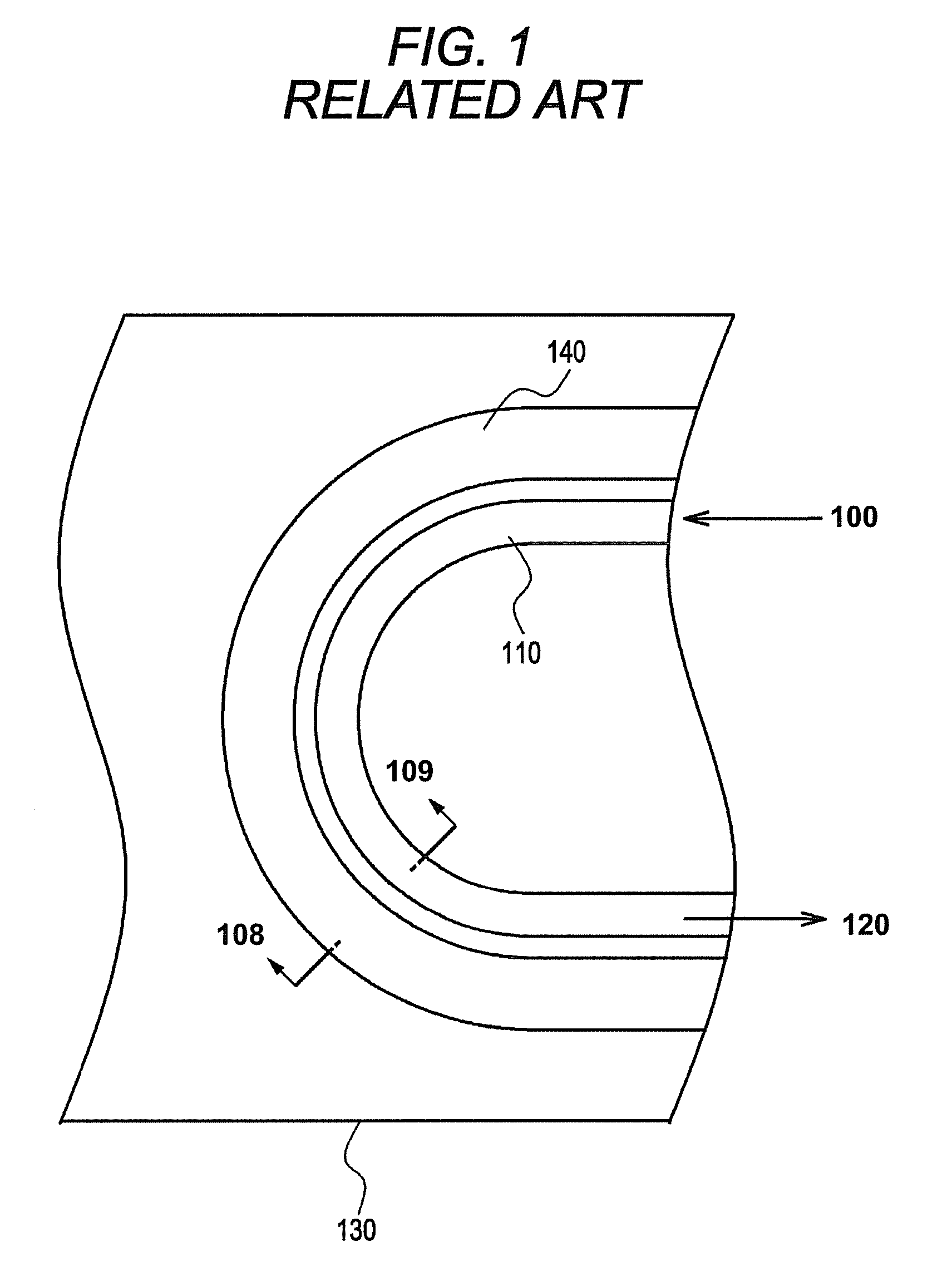
However, the device is lengthened, and a connection loss (up to 1 dB at two points) is generated in a connecting portion of the bending portion of the optical waveguide 110 and the linear optical waveguide.

Method used


Image

  • Optical device and optical transmitter
  • Optical device and optical transmitter
  • Optical device and optical transmitter

Examples


first embodiment

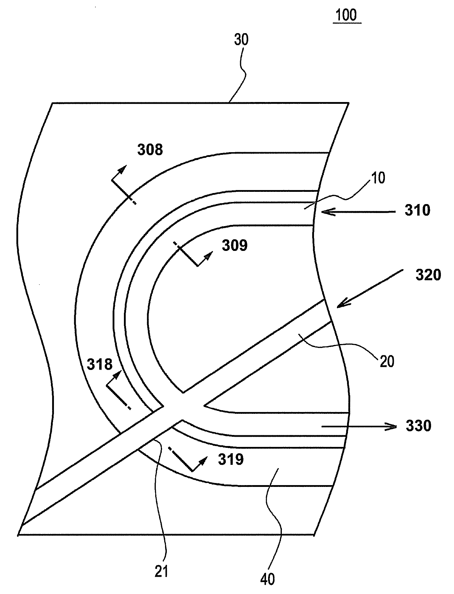
[0035]FIG. 3 illustrates an optical device 100 . FIG. 4A is a sectional view taken on a line 308-309 of FIG. 3, and FIG. 4B is a sectional view taken on a line 318-319 of FIG. 3. The optical device 100 will be described below with reference to FIGS. 3, 4A, and 4B.

[0036]The optical device 100 may have included a first optical waveguide 10 and a second optical waveguide 20 are formed in a substrate 30. For example, the substrate 30 is a LiNbO3 substrate. The first optical waveguide 10 and the second optical waveguide 20 are a diffusion optical waveguide that may be formed by diffusing Ti or the like in the substrate 30. FIG. 3 illustrates inputs 310, 320 and output 330.

[0037]The first optical waveguide 10 may be a bending optical waveguide having a bending portion. The light propagating through the first optical waveguide 10 propagates unevenly through an outside of the bending portion. Therefore, in order to reduce a light propagation loss of the first optical waveguide 10, a groove...

second embodiment

[0050]FIG. 10 illustrates an exemplary optical device 1000. The optical device 1000 differs from the optical device 100 of FIG. 3 in that a first optical waveguide 1008 is provided instead of the first optical waveguide 10 while a second optical waveguide 1009 is provided instead of the second optical waveguide 20. The first optical waveguide 1008 and the second optical waveguide 1009 are a bending optical waveguide having a bending portion. In the second embodiment, the first optical waveguide 1008 and the second optical waveguide 1009 intersect with each other in the bending portions thereof.

[0051]The groove portion 40 may be formed along the outside of the first optical waveguide 1008. A groove portion 41 may be formed along the outside of the second optical waveguide 1009. Accordingly, in the substrate 30, the groove is provided inside the first optical waveguide 1008 and outside the second optical waveguide 1009, and the groove is provided inside the second optical waveguide 10...


PUM


Abstract

An optical device and an optical transmitter are provided. The optical device includes a substrate, a first optical waveguide that may be formed in the substrate and may have a bending portion, and a second optical waveguide that intersects with the bending portion of the first optical waveguide, wherein a groove may be formed outside the bending portion of the first optical waveguide in the substrate.

Description

CROSS REFERENCE TO RELATED APPLICATIONS[0001]This application is related to and claims priority to Japanese Patent Application No. 2009-004804, filed on Jan. 13, 2009, and incorporated herein by reference.BACKGROUND[0002]1. Field[0003]The embodiments discussed herein are directed to an optical device and an optical transmitter.[0004]2. Description of the Related Art[0005]Recently speed enhancement advances have been made in optical communication technology, e.g., a transition from 10 Gb / s to 40 Gb / s. Development of an optical transmitter and an optical receiver, which are used in a communication system of 40 Gb / s or 100 Gb / s is anticipated.[0006]Because a compact optical device in which an optical waveguide is used exhibits excellent characteristics, the optical device is commercially used in various devices such as an optical modulator, an optical receiver, and an optical switch. With progress of the communication system, a increased performance is demanded for the optical waveguid...

Claims


Application Information

Patent Timeline
IPC IPC(8): H04B10/04G02B6/10G02B6/122G02F1/035
CPCG02B6/125G02B2006/12119G02B2006/12097
InventorSHIRAISHI, TAKASHIHASEGAWA, TETSUDOI, MASAHARU
OwnerFUJITSU LTD