
Method for controlling flow and concentration of liquid precursor

a technology of liquid precursor and flow rate control, which is applied in the direction of vacuum evaporation coating, mechanical equipment, transportation and packaging, etc., can solve the problems of inability to use mfc in ald and other processes, inability to accurately control the flow rate of mfc, and inability to reduce the flow rate, so as to achieve accurate control of line pressure and material concentration.

Active Publication Date: 2010-07-15
ASM JAPAN
View PDF53 Cites 369 Cited by
  • Summary
  • Abstract
  • Description
  • Claims
  • Application Information

AI Technical Summary

Benefits of technology

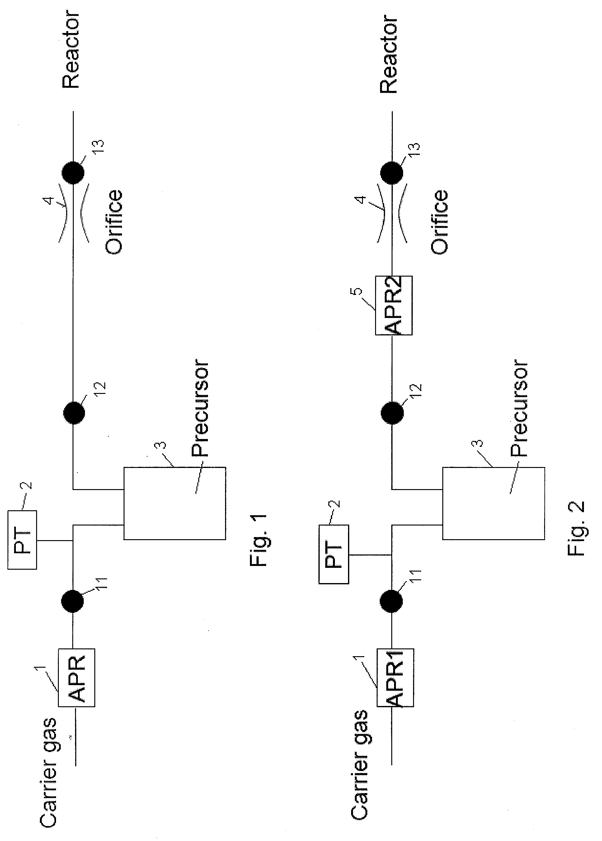
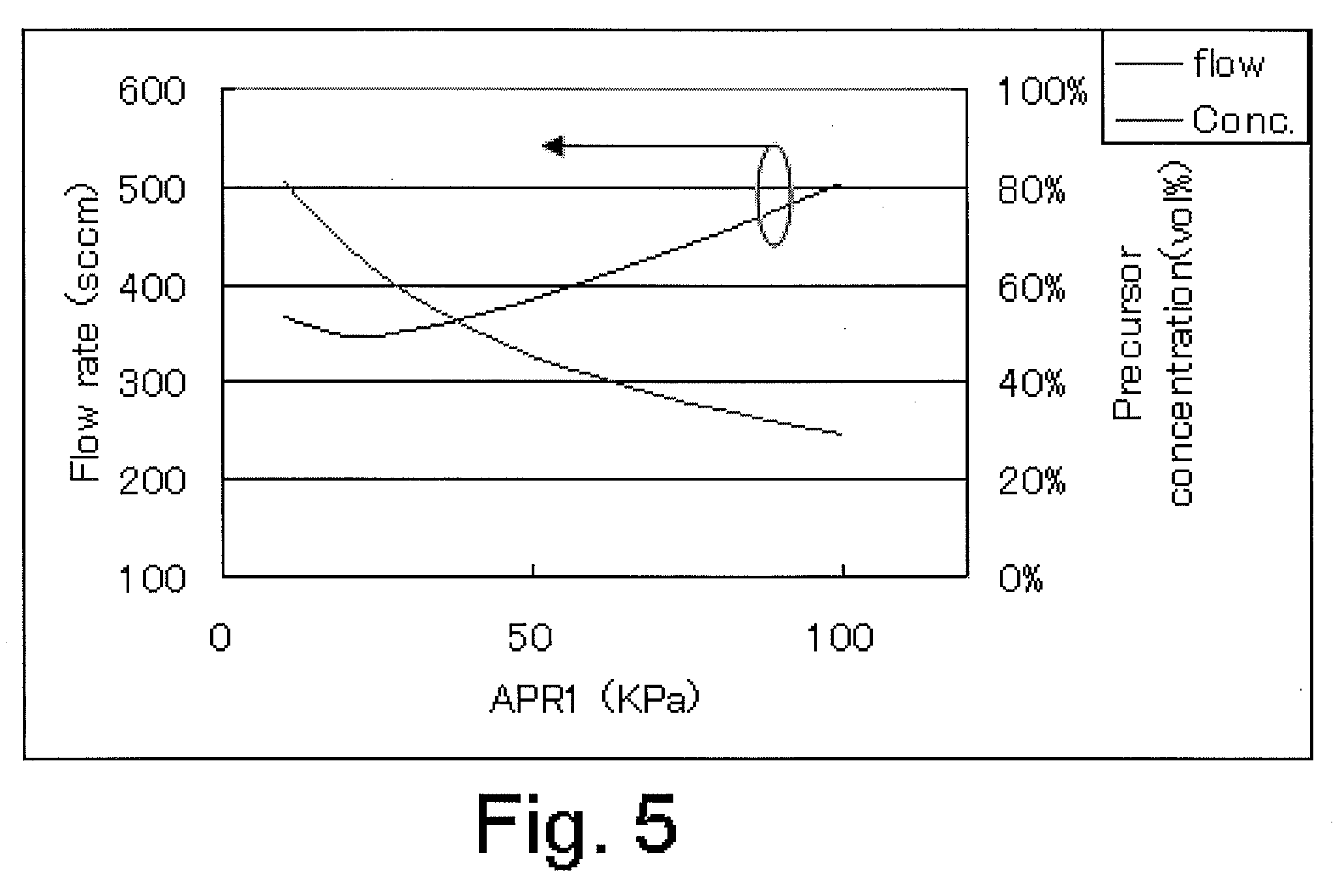
[0009]In an embodiment, the pressure on the primary side of the APR can be raised to the APR operation compensation range by adding the carrier gas pressure, even with liquid materials whose vapor pressure is below the APR operation compensation range (such as 100 kPa or below in pressure on the primary side), and consequently the material concentration can be controlled and the line pressure can also be controlled accurately.

Problems solved by technology

This presents the problem of inaccurate flow rate control by the MFC (Mass Flow Controller) used in traditional CVD, etc., due to a large fluctuation in line pressure.
In other words, while the MFC senses heat transfer inside the controller to control the flow rate at the set level, it requires constant flow because the operating principle of the sensor in the MFC is based on heat transfer, and therefore the MFC cannot be used in ALD and other processes where gas is supplied and stopped frequently.
With liquid materials of high vapor pressure, the flow rate cannot be lowered because the line pressure cannot be lowered to or below the material vapor pressure.
Furthermore, the carrier gas pressure need to be increased to lower the material concentration, which causes the flow rate to rise.

Method used


Image

  • Method for controlling flow and concentration of liquid precursor
  • Method for controlling flow and concentration of liquid precursor
  • Method for controlling flow and concentration of liquid precursor

Examples


Embodiment Construction

[0021]The present invention will be explained below with reference to embodiments which are not intended to limit the present invention.

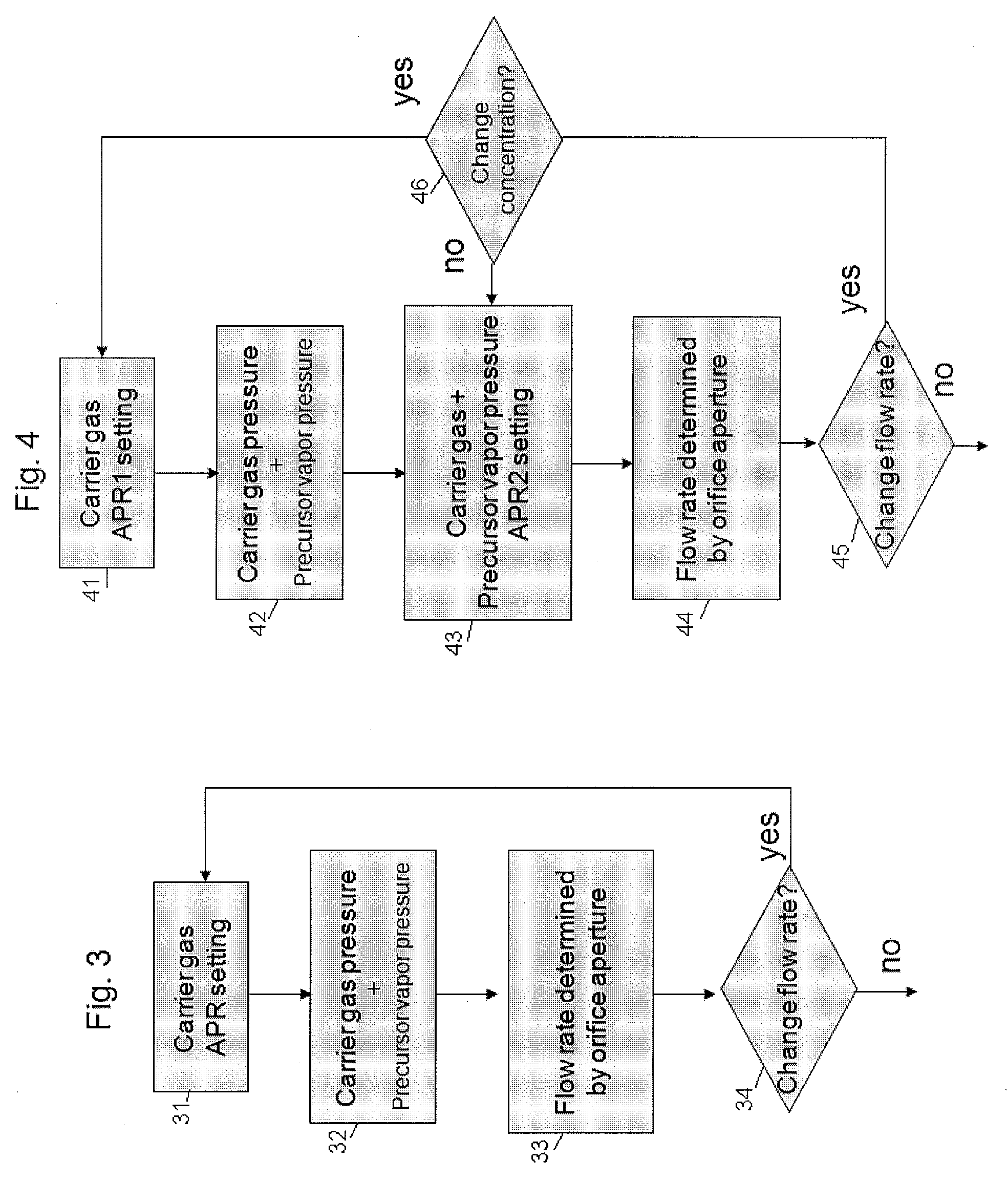
[0022]One of the disclosed embodiments provides a method for controlling flow and concentration of a liquid precursor, comprising: (i) supplying a carrier gas to a first auto-pressure regulator and outputting therefrom the carrier gas at a first pressure to an inlet of a precursor reservoir that stores a vaporized precursor, thereby outputting a mixture of the vaporized precursor and the carrier gas from the precursor reservoir through an outlet of the precursor reservoir, said first auto-pressure regulator being provided upstream of the precursor reservoir; and (ii) supplying the mixture of the vaporized precursor and the carrier gas to a second auto-pressure regulator and outputting therefrom the mixture at a second pressure to a reactor via an orifice, said second auto-pressure regulator being provided downstream of the precursor reservoir and sa...


PUM

PropertyMeasurementUnit
Timeaaaaaaaaaa
Partial pressureaaaaaaaaaa
Temperatureaaaaaaaaaa

Abstract

A method for controlling flow and concentration of a liquid precursor includes: supplying a carrier gas to a first auto-pressure regulator and outputting therefrom the carrier gas at a first pressure to a precursor reservoir; outputting the mixture of the vaporized precursor and the carrier gas from the precursor reservoir; and supplying the mixture to a second auto-pressure regulator and outputting therefrom the mixture at a second pressure to a reactor via an orifice.

Description

BACKGROUND [0001]1. Field of the Invention[0002]The present invention relates to a method for supplying a liquid material used for deposition of a thin film by, for example, Atomic Layer Deposition (hereinafter referred to as “ALD”). In particular, the present invention relates to a method for controlling the concentration and flow rate of a material of high vapor pressure.[0003]2. Description of the Related Art[0004]Conventionally, film deposition by ALD is performed at short intervals of 0.1 to 1 second in order to switch the precursor and reactant by opening / closing the valves in the gas supply lines.[0005]This presents the problem of inaccurate flow rate control by the MFC (Mass Flow Controller) used in traditional CVD, etc., due to a large fluctuation in line pressure. Under ALD, therefore, the APR (Auto Pressure Regulator) is used to maintain a constant line pressure, while an orifice, etc., provided at the entrance of the reaction chamber is used to control the flow rate. In ...

Claims


Application Information

Patent Timeline
IPC IPC(8): C23C16/455F17D1/16
CPCC23C16/45544F17D1/16C23C16/45561Y10T137/0396H01L21/0262
Inventor SHIMIZU, AKIRAKOBAYASHI, AKIKOKANAYAMA, HIROKI
Owner ASM JAPAN
Learn More