Power generating system

Active Publication Date: 2010-07-15
PANASONIC CORP
View PDF6 Cites 3 Cited by
  • Summary
  • Abstract
  • Description
  • Claims
  • Application Information

AI Technical Summary

Benefits of technology

[0023]In accordance with the power generating system of the present invention, the complexity of the wires connecting respective devices can be reduced while suppress

Problems solved by technology

In addition, since the control device is separated from the gas passage chamber by the dividing wall, i

Method used


Image

  • Power generating system
  • Power generating system

Examples


embodiment 1

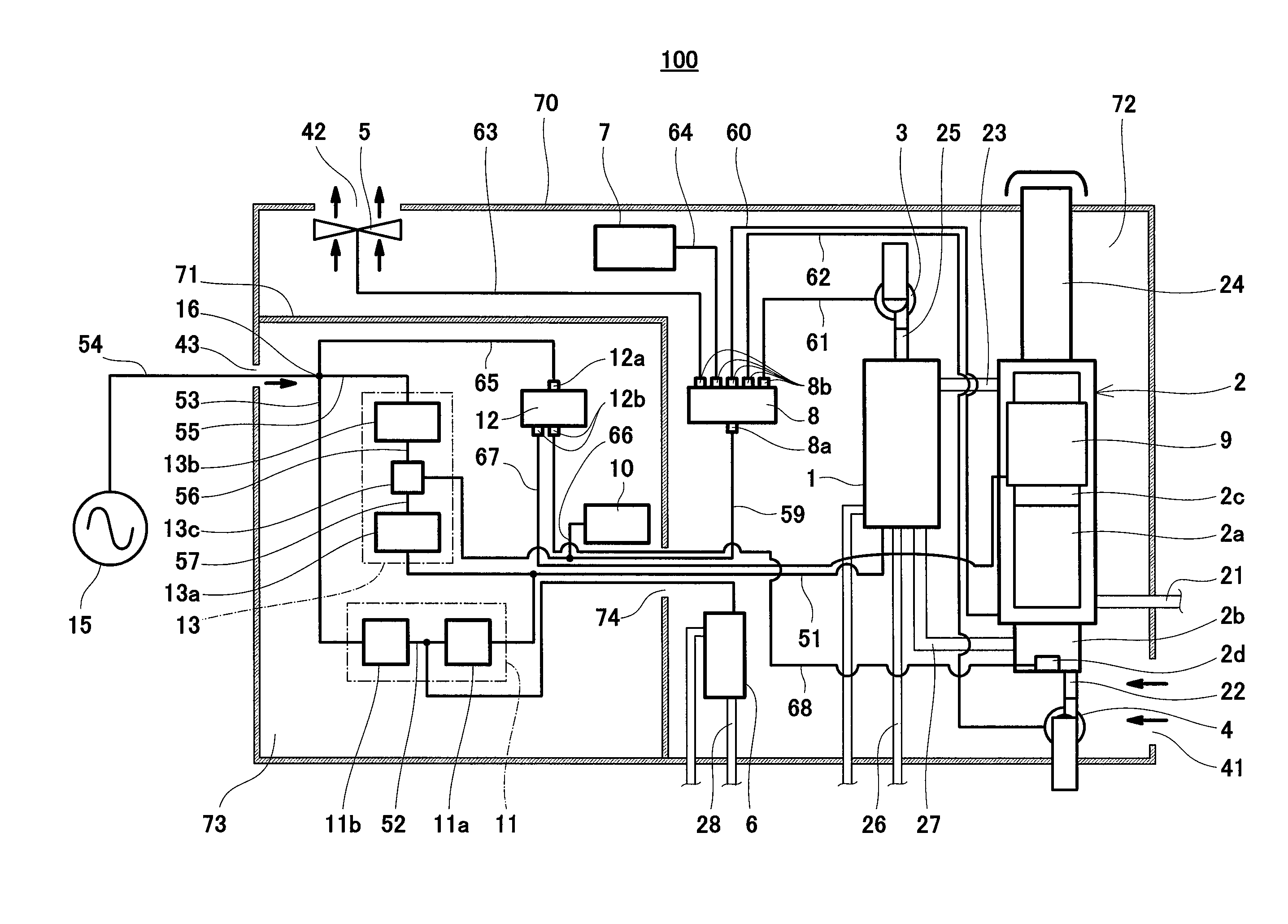
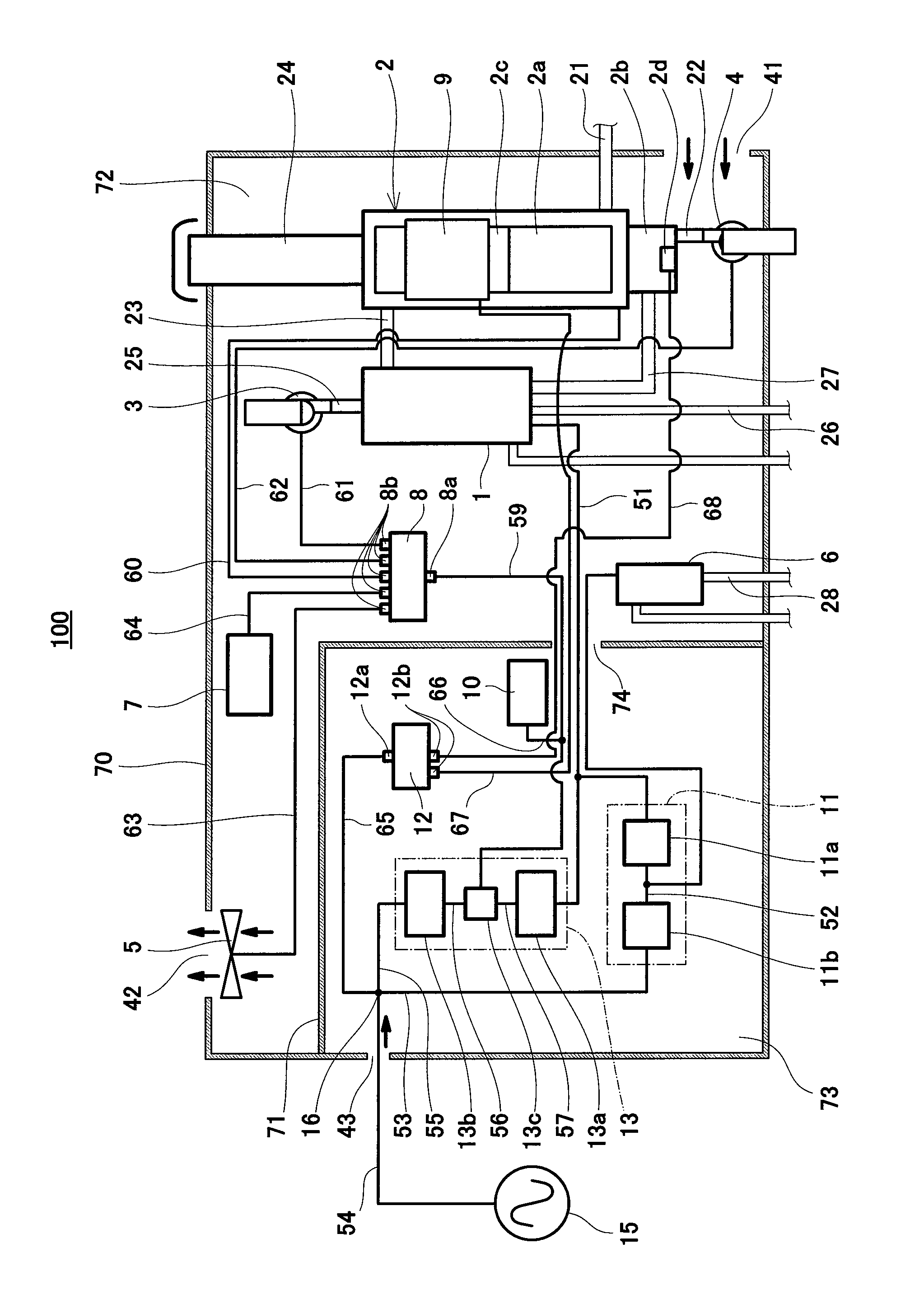
[0087]FIG. 1 is a schematic diagram showing a schematic configuration of a power generating system according to Embodiment 1 of the present invention.

[0088]As shown in FIG. 1, a power generating system 100 according to Embodiment 1 includes a package 70 constituted by a housing. An internal space of the package 70 is divided into a first space 72 and a second space 73 by a dividing wall 71. A through hole 74 is formed at an appropriate portion of the dividing wall 71 so as to penetrate the dividing wall 71 in a thickness direction thereof. The through hole 74 forms a communicating portion 74 through which the first space 72 and the second space 73 are communicated with each other. Wires electrically connecting between devices in the first space 72 and devices in the second space are arranged to fill in an internal space of the communicating portion 74. With this, a gas hardly flows between the first space 72 and the second space 73 through the communicating portion 74. The respectiv...


PUM


Abstract

A power generating system of the present invention includes: a package (70); a power generator (1); a combustible gas passage (23); a first device configured to operate by a first voltage using a DC power generated by the power generator (1); a second power supply circuit (13) configured to generate the DC power of the first voltage; a first connecting unit (8) arranged between the first device and the second power supply circuit (13); a control circuit (7) configured to control the first device using the DC power of the first voltage; and a first power supply circuit (11) configured to generate a power of a second voltage higher than the first voltage, and the package (70) is divided by a dividing wall (71) into a first space (72) in which the power generator (1), the combustible gas passage (23), the first device, the first connecting unit (8), and the control circuit (7) are arranged and a second space (73) in which the first power supply circuit (11) and the second power supply circuit (13) are arranged.

Description

TECHNICAL FIELD[0001]The present invention relates to a power generating system, and particularly to the configuration of a power generating system in which a fuel cell is arranged in a package.BACKGROUND ART[0002]A fuel cell system is a system configured to generate electricity and heat at the same time by causing a hydrogen-containing fuel gas obtained by reforming a material gas, such as a city gas, and an oxygen-containing oxidizing gas, such as air, to electrochemically react with each other and to supply the generated electricity to an external electric power load (such as a domestic electrical apparatus).[0003]Known is a fuel cell system configured such that the entire fuel cell system is arranged in a package to facilitate delivery, installation, and the like in a case where the fuel cell system is used as a mobile power supply or a distributed (on-site) power supply (see Patent Document 1 for example).[0004]In accordance with the fuel cell system disclosed in Patent Documen...

Claims


Application Information

Patent Timeline
IPC IPC(8): H01M8/18H01M8/02
CPCH01M8/04089H01M8/04925H01M8/0618H01M8/2475Y02B90/18H01M2250/30Y02E60/50Y02B90/14H01M2250/10Y02B90/10
Inventor TAKUBO, HIDETOSHIKATOU, MOTOMICHI
Owner PANASONIC CORP
Why Eureka
Try Eureka