Garbage container provided with a compactor

a technology of compactor and garbage container, which is applied in the direction of containers, lids, caps, etc., can solve the problems of cumbersome form of pressing element and related operating rod, excessive volume reduction, and difficulty in inserting cumbersome waste, etc., to achieve the effect of compacting the collected waste, reducing the force, and being convenient to us

Inactive Publication Date: 2010-07-22
SITES
View PDF3 Cites 8 Cited by
  • Summary
  • Abstract
  • Description
  • Claims
  • Application Information

AI Technical Summary

Benefits of technology

[0027]According to a third embodiment of the present invention, the compactor may be manufactured separately from the main body of the container. In this way the compactor may be sold separately so as to be coupled to existing containers of the user. For instance, the compactor may be commercialized together with a lid which can fit common containers for domestic use.
[0028]The container according to the present invention allows for effectively compacting the collected wastes, with minimum force, being at the same time easy to use, cheap and reliable.
[0029]Thanks to the pressing element being tiltable with respect to the vertical, insertion of the wastes within the main body of the container is easy, that is the pressing element obstructs the container inlet only to the minimum extent. This feature makes the container according to the present invention particularly suitable for the domestic use, for example having a volume comprised between 15 and 40 litres.

Problems solved by technology

Firstly, the assembly formed by the pressing element and the related operating rod is cumbersome, i.e. it excessively reduces the volume that can be used for inserting the wastes into the container.
In particular, when the lid is hinged to the container body and is rotated to access the internal volume of the container, the pressing element partially obstructs the container inlet, thereby making difficult to insert cumbersome wastes.
Secondarily, the weight of the compactor increases the weight of the lid, which is thereby uncomfortable to be upraised, for instance when replacing the garbage bag.
Another drawback of the traditional solutions comes from the fact that the force needed for effectively operating the compactor may be high, to the detriment of the practicality of the functioning.

Method used


Image

  • Garbage container provided with a compactor
  • Garbage container provided with a compactor
  • Garbage container provided with a compactor

Examples


first embodiment

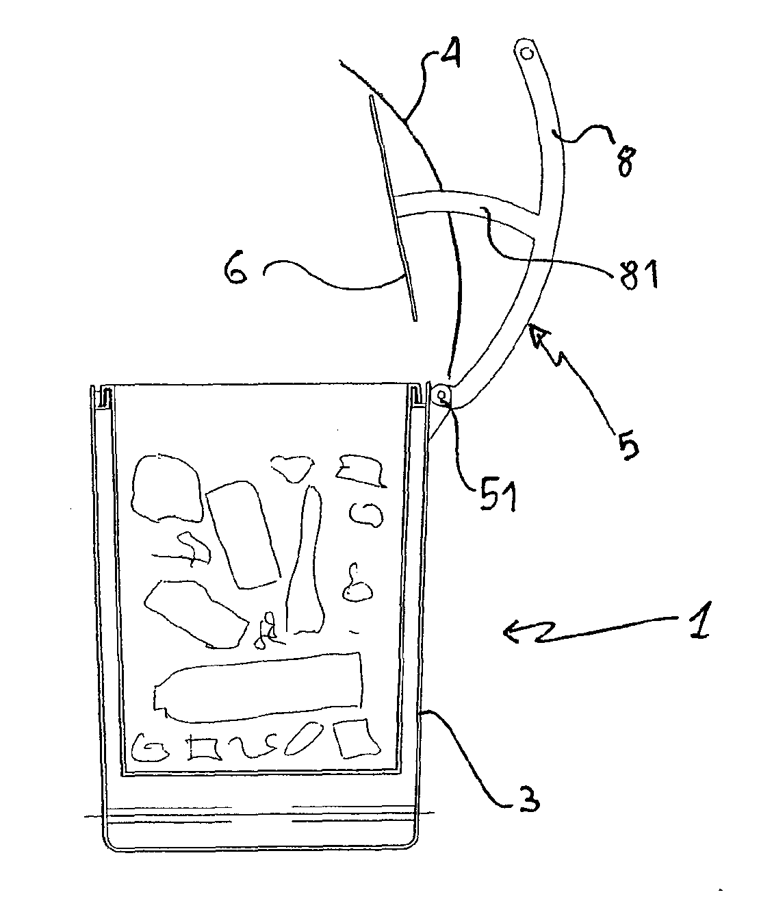
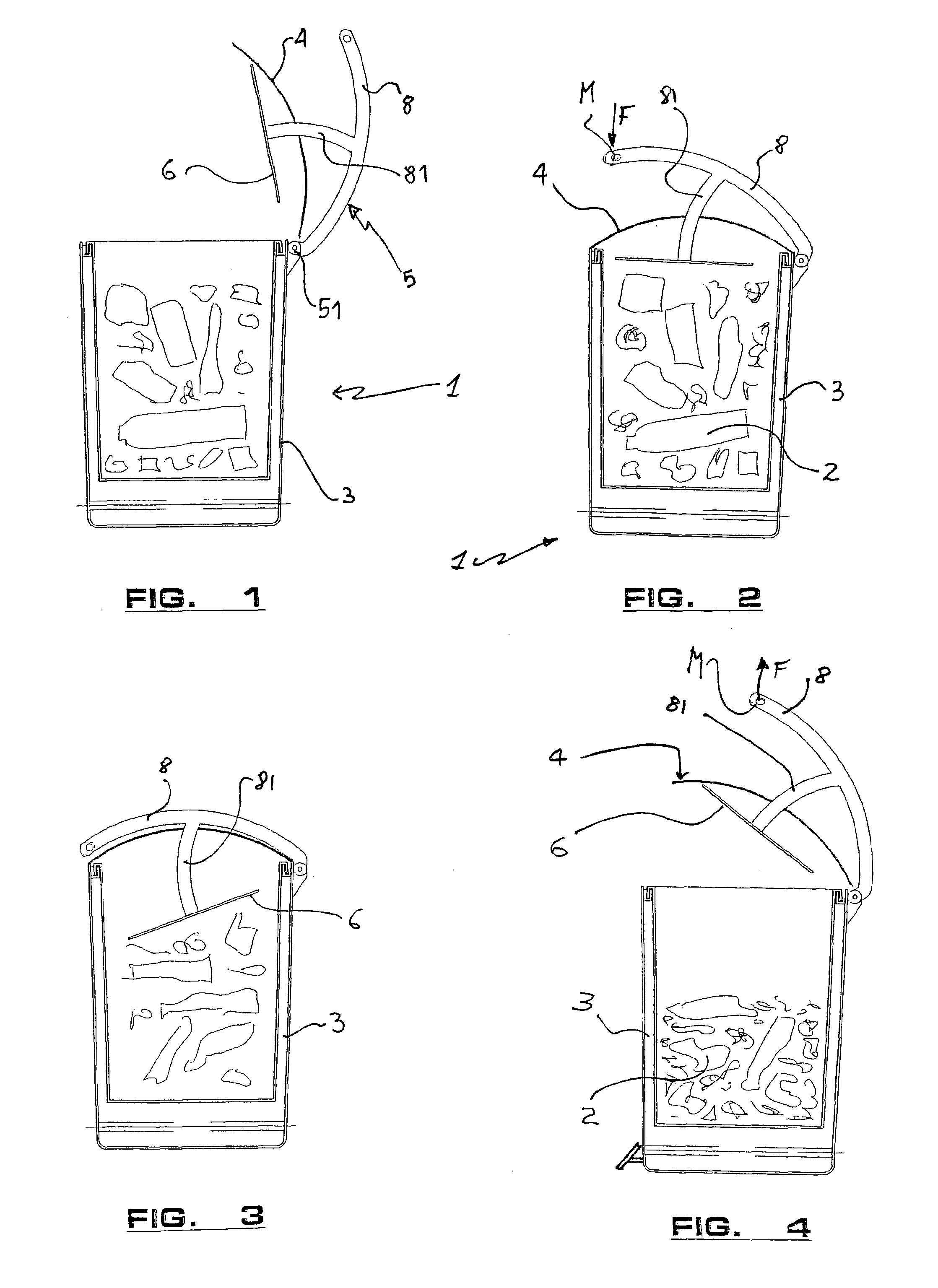
[0037]With reference to the FIGS. 1-5, it is shown a container 1 according to the present invention. The container 1 comprises a main body 3 intended to lodge waste 2 of various types, preferably in a plastic bag inserted within the body 3. The container also comprises a lid 4 moveable to allow insertion of wastes 2 into the container.

[0038]The main body 3 of the container may have a generic circular section, or it may be square, rectangular, hexagonal, etc. The base of the container may be closed, open, flat or curved toward the inside of the same container 1.

[0039]The side wall of the main body 3 may be closed, or may provide for one ore more openings. For instance, the side wall of the body 3 may be shaped as a rigid net having small or large meshes. The openings allow for circulation of the air.

[0040]The openings on the side wall of the main body 3 may be wide to the extent that the same side wall may be configured as one or more vertical posts which support the container inlet,...

second embodiment

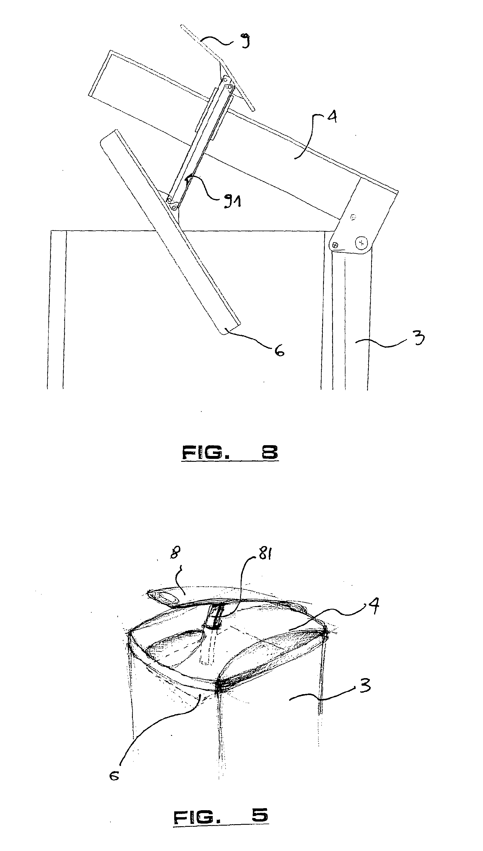
[0050]The FIGS. 6-8 refer to the container according to the present invention wherein the vertical displacement of the pressing element 6 and rotation about a vertical line are independent one from the other.

[0051]The operating lever 9 of the compactor 5 is couplet to the pressing element 6 by means of an articulated system 91 slidable in a suitable seat 41 of the lid 4, preferably provided in central position.

[0052]The articulated system 91 allows to transfer to the pressing element 6 the vertical displacements and rotations imparted by the user to the lever 9. In the embodiment shown in the FIGS. 6-8, the articulated system 91 comprises two parallel arms 92, 93, both being hinged to the ends, respectively to the lever 9 and the pressing element 6. The articulated system 91 is slidable in the seat 41 provided within the lid 4.

[0053]Any rotation imparted to the lever 9 in the direction of the arrow R (FIG. 5), about the hinge 931 of the arm 93, causes the arm 92 to move upwardly and...

third embodiment

[0059]The FIGS. 10 and 11 show the container according to the present invention, wherein the compactor 5 is manufactured as a separate element from the body 3 of the container. In this way the compactor 5 may be sold separately from the body 3 of the container, for instance together with an universal lid 4, and may be applied to containers already used by the users.

[0060]The FIG. 10 shows a compactor 5 in the phase of coupling with the body 3 of the container 1, while the FIG. 11 shows the compactor 5 which fits (that is it overlaps) onto the edge of the body 3 of the same container, i.e. when the coupling is accomplished. The higher is the overlapping of the base 52 of the compactor onto the inlet of the body 3 of the container, the higher is the stability of the coupling.

[0061]The container 1 according to the present invention is simple to manufacture and, more than all, it allows to effectively compact the wastes 2 collected therein, without the pressing element 6 interfering wit...


PUM


Abstract

The present invention concerns a container (1) for wastes (2), in particular for collecting wastes in the domestic field. The container comprises a main body (3), a lid (4) associable to the main body and a compactor (5) provided with a pressing element (6), moveable within the main body (3) to compact the wastes (2) collected therein. The pressing element is manually operated from the outside of the container (1) through suitable mechanical means. Advantageously, the operating means comprises a lever (8, 9) which can be operated by the user to vary the vertical position and the inclination of the pressing element.

Description

FIELD OF THE INVENTION[0001]The present invention relates to a garbage container provided with a compactor, in particular relates to a garbage container, mostly for domestic use, provided with a manual compactor for wastes.PRIOR ART[0002]Several kinds of containers have been made available provided with a compactor, to be operated by the user, which allow for reducing the volume of the collected garbage.[0003]The Italian utility model application IT MI 2004U000043 discloses a container for collecting domestic wastes, provided with a main body, in which for instance a bag can be positioned, and a lid connected to said body. The lid is provided with a compactor manually operable from its outside. The compactor comprises a pressing element, that is a disk intended to compact the wastes collected in the container body, a rod for operating the pressing element, slidingly arranged through the lid, in a central position, and a handle fixed to the rod. Normally the pressing element remains ...

Claims


Application Information

Patent Timeline
Patent Type & Authority Applications(United States)
IPC IPC(8): B65F1/16B65D43/16B65D43/26B65D51/24B30B7/00
CPCB65F1/1623B65F1/1405
Inventor TURINA, ANNA
Owner SITES
Why Eureka
Try Eureka