Fly reel spool

a technology of reels and spools, applied in the field of fly reels, can solve the problems of high price, and achieve the effects of reducing the purchase price of consumers, high price, and cost saving

Inactive Publication Date: 2010-07-22
KANG SEOK WOON +1
View PDF11 Cites 9 Cited by
  • Summary
  • Abstract
  • Description
  • Claims
  • Application Information

AI Technical Summary

Benefits of technology

[0011]According to embodiments of the present invention, a part of the fly reel on or from which the fish line is wound or unwound is constructed with the rotary frame and the winding drum, which are attached to and detached from each other by one touch, so that the winding drum of the fly reel on which the fish line is directly wound can be separately purchased to reduce the purchase price for consumers. This is desirable for consumers in terms of cost. Since the fly reel is a type of high grade leisure article, its price is high. In this embodiment of the present invention, since the winding drum on which the fish line is directly wound can be separately purchased, the consumers can experience a significant cost saving effect. Due to these features, a positive response from the consumers can be expected.
[0012]In addition, the rotary frame and the winding drum are securely coupled with each other by the locking balls in the locked position, and the elastic sheet made of elastic material such as silicone is installed inside the housing from and into which the locking balls can protrude and retract so as to elastically hold the locking balls. Thereby, the fly reel spool can efficiently operate with high reliability since the main parts detachably supporting the rotary frame and the winding drum can be more easily assembled and have a more stable structure.
[0013]According to embodiments of the invention, the winding drum is coupled by one touch to the rotary frame (i.e., a main part) using the locking members, and the annular spring fitted into the inner circumference of the winding drum using its own elastic force elastically holds the locking members in the locked position. The locking part can be improved to have a simpler structure, and a more rapid assembly operation can be expected.
[0014]According to embodiments of the invention, the locking members are formed in the rotary frame, the locking protrusions are formed in the locking members, and the ball-catching protrusion is formed on the winding drum, such that the winding drum and the rotary frame are securely coupled with each other by engagement between the locking members of the rotary frame and the ball-catching protrusion. Thereby, the main parts detachably supporting the rotary frame and the winding drum can be more easily assembled and have a more stable structure.
[0015]In addition, the main part detachably supporting the rotary frame and the winding drum is implemented with the wire spring produced by bending a single wire, and the elastic bends of the wire spring are caught on the ball-catching protrusion on the inner circumference of the winding drum. Thereby, the main part can be realized with a simpler structure.

Problems solved by technology

Since the fly reel is a type of high grade leisure article, its price is high.

Method used


Image

  • Fly reel spool
  • Fly reel spool
  • Fly reel spool

Examples


Embodiment Construction

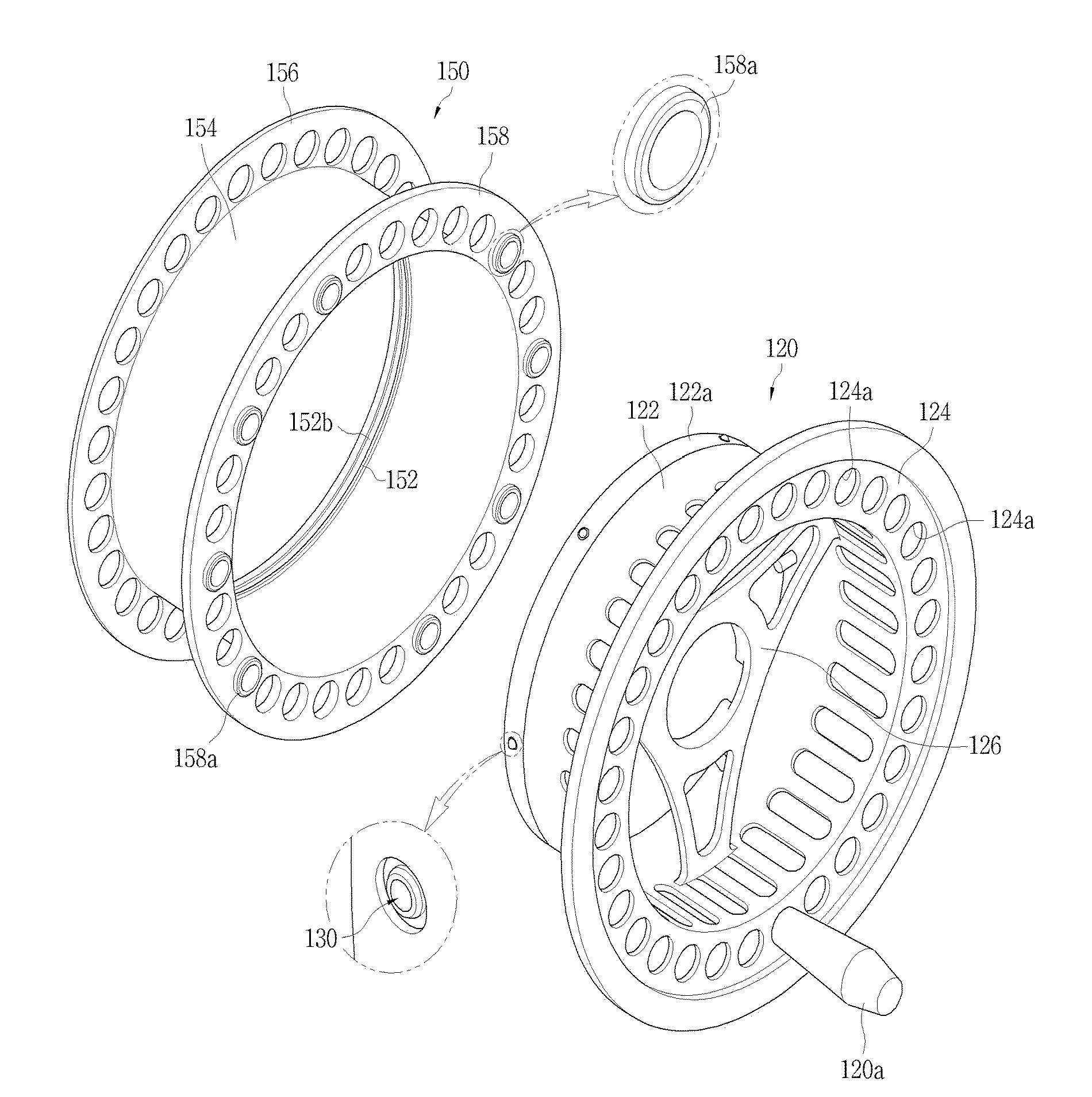
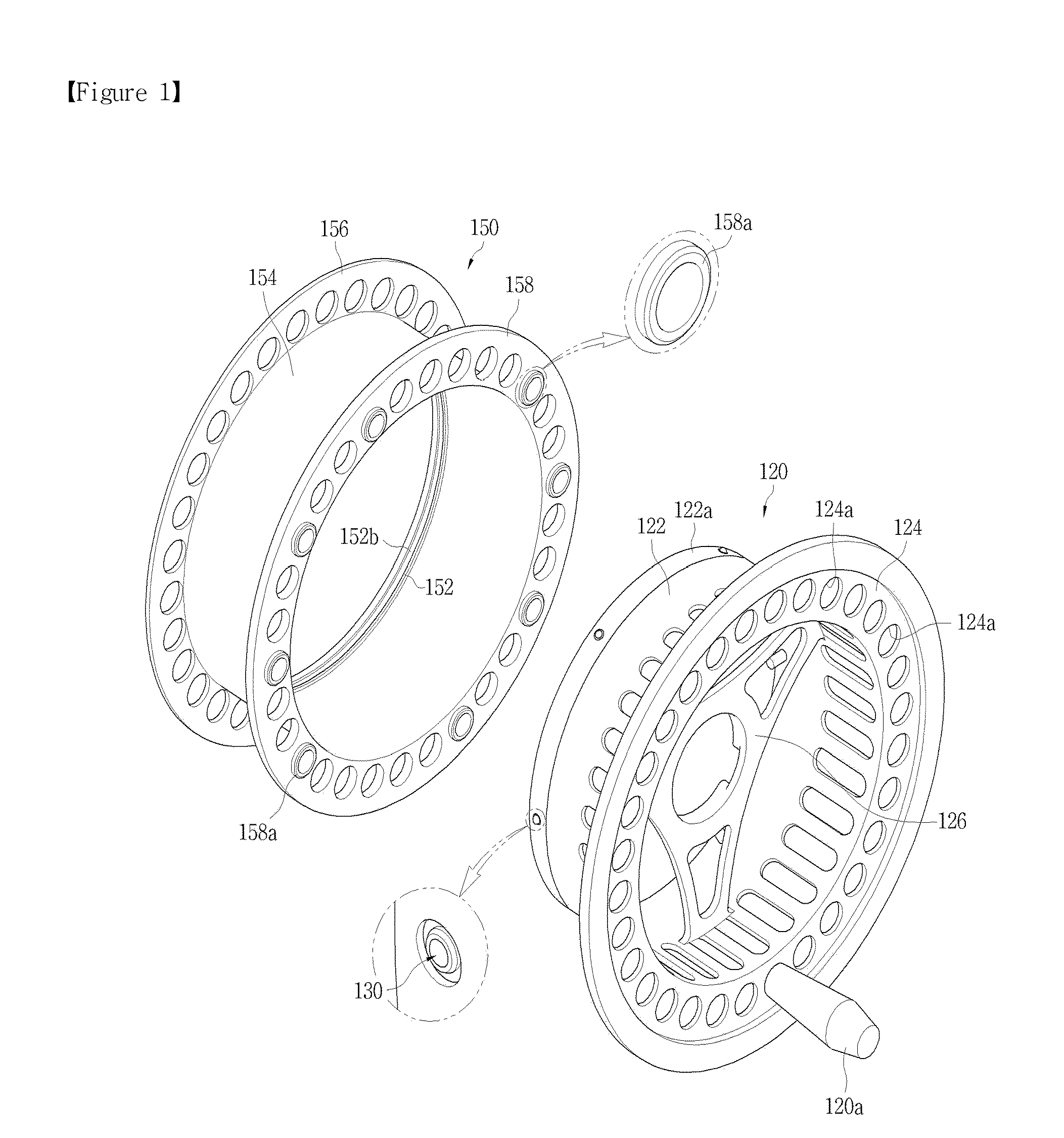
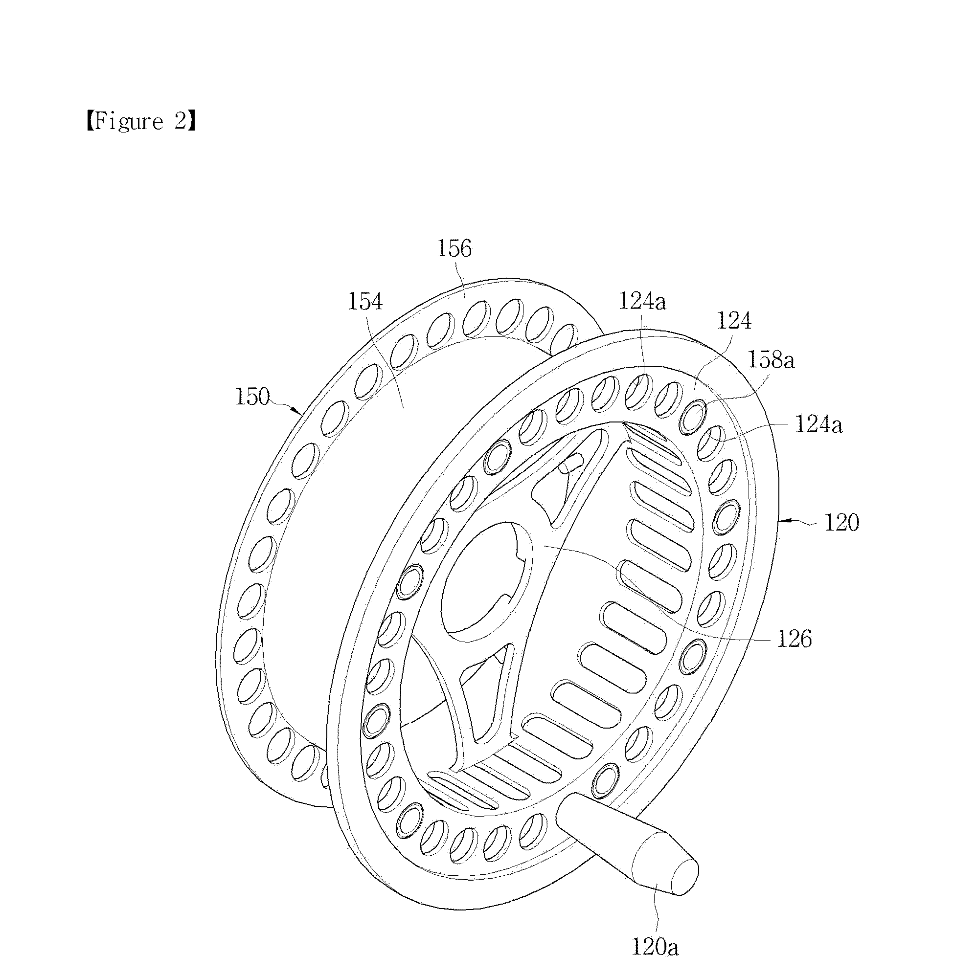
[0043]The present invention will now be described more fully hereinafter with reference to the accompanying drawings, in which exemplary embodiments thereof are shown.

[0044]FIG. 1 is an exploded perspective view illustrating a spool according to an exemplary embodiment of the present invention, FIG. 2 is an assembled perspective view of the spool shown in FIG. 1, FIG. 3 is a cross-sectional view illustrating main parts of the spool shown in FIG. 1, FIG. 4 is a cross-sectional view illustrating the structure of a drag unit of the spool shown in FIG. 1, and FIG. 5 is an exploded perspective view illustrating a fly reel having the spool shown in FIG. 1. As shown in the figures, the present invention includes a rotary frame 120, a winding drum 150, locking balls 130 and elastic supporting means. The rotary frame 120 is rotatably mounted inside a cylindrical frame 110, which has a shaft member 112 in the central portion thereof, via a drag unit, and the winding drum 150 is detachably cou...


PUM


Abstract

A fly reel spool rotatably coupled with a frame mounted on a fishing rod to wind a fish line includes a rotary frame rotatably coupled inside the frame; a winding drum having a ball-catching protrusion on an inner circumference coupling with the rotary frame, the winding drum configured such that the fish line is wound on or unwound from an outer circumference; a locking ball installed in an outer circumference of the rotary frame to protrude from and retract into the rotary frame; elastic means for elastically holding the locking ball so that it protrudes from the outer circumference of the rotary frame, whereby the locking ball is caught by one touch on the ball-catching protrusion on the inner circumference of the winding drum when the rotary frame is coupled with the winding drum, and stopping means for supporting the winding drum and the rotary frame to rotate together.

Description

BACKGROUND OF THE INVENTION[0001]1. Field of the Invention[0002]The present invention relates, in general, to a fly reel spool and, more particularly, to a fly reel spool which is advantageous for consumers in terms of cost savings since main parts for winding or unwinding a fish line such as a rotary frame and a winding drum can be separated from each other, and to a fly reel having this spool.[0003]2. Description of the Related Art[0004]Fly fishing is a method of fishing for bass, trout, etc., which feed on water insects or small fish. Fly fishing uses a fly hook resembling the shape of an aquatic insect made of a bird feather or animal hair to lure fish to bite the fly hook.[0005]A fly reel of a fly fishing rod includes, as main parts, a spool for winding or unwinding a fish line, a frame rotatably supporting the spool and a bearing set (including a one-way bearing) for controlling the rotating rate of the spool. The fish line can be rapidly wound on the spool by turning a handle...

Claims


Application Information

Patent Timeline
Patent Type & Authority Applications(United States)
IPC IPC(8): A01K89/016
CPCA01K89/016A01K89/0162A01K89/01931
Inventor KANG, SEOK WOONKANG, SUK YOUNG
Owner KANG SEOK WOON
Why Eureka
Try Eureka