
Automatic wood board conveying device

A technology for conveying equipment and boards, applied in conveyors, mechanical equipment, conveyor objects, etc., can solve the problems of increased procurement costs, inability to adjust, high maintenance costs, etc., to reduce unnecessary expenses, reduce labor input, The effect of improving work efficiency

Pending Publication Date: 2018-08-14
HARBIN UNIV OF COMMERCE
View PDF6 Cites 4 Cited by
  • Summary
  • Abstract
  • Description
  • Claims
  • Application Information

AI Technical Summary

Problems solved by technology

[0002] At present, the demand for automation equipment in the market is increasing day by day, and most of the existing plank conveying schemes on the market are supplied manually or through complex multi-power distributed mechanisms, such as manipulators controlled by hydraulic pressure or pneumatic pressure to complete tasks, and only Able to feed a single size of wood, can not be adjusted flexibly
In addition, considering the product characteristics of small width and thickness of wooden boards, the wooden boards are easily damaged during the process of being fed by the automatic manipulator, the feeding effect is not ideal, and the conveying efficiency is low; and if the manipulator controlled by hydraulic pressure or air pressure is used, the required The working area will be greatly increased. Since the manipulator itself has the characteristics of high technological content, it will bring high additional maintenance costs while increasing the purchase cost of the enterprise.

Method used


Image

  • Automatic wood board conveying device
  • Automatic wood board conveying device
  • Automatic wood board conveying device

Examples


Embodiment 1

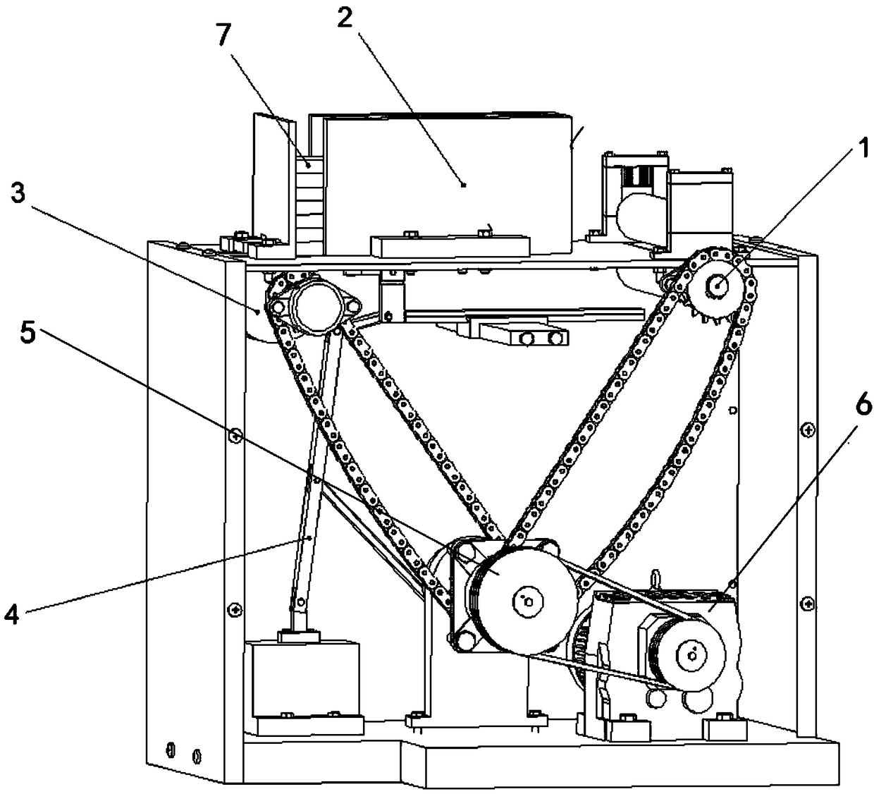
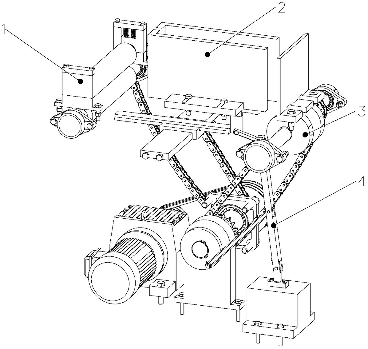
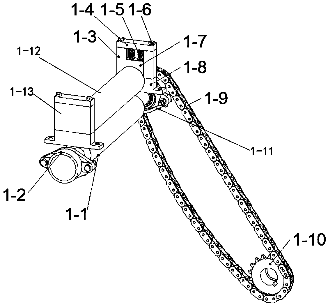
[0021] like Figure 1-2 As shown, an automatic wood board conveying equipment includes a frame, a wood board conveying mechanism 1, a wood board accommodating mechanism 2, a wood board jacking mechanism 3, a wood board pushing mechanism 4, a transmission mechanism 5 and a power mechanism 6, and the power mechanism 6 and the transmission mechanism 5 Connected, many stacks of wooden boards are placed in the wooden board accommodating mechanism 2, the wooden board accommodating mechanism 2 is located on the upper rack, the board conveying mechanism 1 is located in front of the upper rack and the wooden board accommodating mechanism 2, and the board pushing mechanism 4 and the wooden board are jacked up. The mechanism 3 is located in the frame respectively, below the wood board accommodating mechanism 2, the transmission mechanism 5 and the power mechanism 6 are located on the bottom frame, the wood board conveying mechanism 1, the wood board jacking mechanism 3 and the wood board ...


PUM


Abstract

The invention relates to an automatic wood board conveying device. The automatic wood board conveying device comprises a machine frame, a wood board conveying mechanism, a wood board accommodating mechanism, a wood board jacking mechanism, a wood board pushing mechanism, a transmission mechanism and a power mechanism. The wood board accommodating mechanism is positioned on an upper machine frame,the wood board conveying mechanism is positioned in front of the upper machine frame and the wood board accommodating mechanism, and the wood board pushing mechanism and the wood board jacking mechanism are correspondingly positioned in the machine frame and below the wood board accommodating mechanism. The transmission mechanism and the power mechanism are positioned on a bottom machine frame, the wood board conveying mechanism, the wood board jacking mechanism and the wood board pushing mechanism are correspondingly connected with the transmission mechanism, and wood boards at the bottom layer are sequentially pushed back and forth through the wood board pushing mechanism, and enter the wood board conveying mechanism, at the same time, the wood board jacking mechanism jacks up the rest of the wood boards to reduce the pushing resistance of the wood board pushing mechanism. The automatic conveying of the wood boards with different sizes is realized, the labor force input is reduced, the safety and work efficiency are improved, and traditional manual operation of the wood boards is changed.

Description

technical field [0001] The invention relates to the field of wood conveying, in particular to an automatic wood board conveying device Background technique [0002] At present, the market's demand for automation equipment is increasing, and the existing plank conveying solutions on the market are mostly manual supply or through complex multi-power distributed mechanisms, such as the use of hydraulic or pneumatically controlled manipulators to complete tasks, and only It can supply a single size of wood, and it cannot be adjusted flexibly. In addition, considering the product characteristics of small board width and small thickness, the board is easily damaged in the process of being fed by the automatic manipulator, the feeding effect is not ideal, and the conveying efficiency is low; and if a hydraulic or pneumatically controlled manipulator is used, the required The working area will be greatly increased. Due to the high technological content of the manipulator itself, it...

Claims


Application Information

Patent Timeline
Patent Type & Authority Applications(China)
IPC IPC(8): B65G35/00B65G47/82F16H37/12
CPCF16H37/12B65G35/00B65G47/82B65G2201/0282
Inventor 晏祖根杨军福孙智慧卜迟武
Owner HARBIN UNIV OF COMMERCE
Learn More