Belt Tensioner With a Cup-Shaped Drive Piston

a technology of drive piston and seat belt, which is applied in the direction of vehicle safety belts, belt retractors, vehicle components, etc., can solve the problems of high frictional force, high cost of mounting sealing rings, etc., and achieves the effect of reducing installation space, good sealing, and improving the tightness of the drive piston relative to the tubular housing

Inactive Publication Date: 2010-07-22
AUTOLIV DEV AB
View PDF15 Cites 8 Cited by
  • Summary
  • Abstract
  • Description
  • Claims
  • Application Information

AI Technical Summary

Benefits of technology

[0005]The present invention is therefore based upon the objective of simplifying the design of the drive piston and reducing the frictional forces originating from the forward movement of the drive piston through the tubular housing in connection with a belt pretensioner having the above mentioned representative features.
[0007]In its fundamental idea, the present invention provides that the drive piston is configured like a hollow cup, and at its closed end side is provided with an inwardly directed vaulting or depression that is adapted to the contour of a solid ball. The present invention is associated with the advantage that the drive piston forms a part to be produced in a single piece which can be manufactured in one operation without additional processing. Due to the gas pressure prevailing inside the cup-shaped drive piston, when the pretensioner drive is triggered, the rear edge of the drive piston is pressed against the wall of the tubular housing that forms the channel so that a good seal exists. A further advantage is that the cup-shaped drive piston has a preset volume for the gas volume that is formed when the pretensioner drive is triggered, as a result of which, taking into consideration the overall required gas pressure, the installation space is minimized. The depression configured in the closed end face of the drive piston provides for good guidance of the series of solid balls arranged in the channel of the tubular housing.
[0008]According to an embodiment of the present invention, it is provided that the cup-shaped drive piston has a conical shape tapering in the direction of the solid bodies. With this, the tightness of the drive piston relative to the tubular housing is improved by the tendency of the conical shape of the piston to expand induced by the gas pressure. In this connection, according to an embodiment of the present invention, it may be provided that the conical shape of the drive piston is graduated at least once along its longitudinal axis.
[0009]It may specifically be provided that at its end opposite the end face, the drive piston presses against the inner surface of the tubular housing receiving the channel with a linear sealing rim. By means of the quasi ring-shaped attachment of the rear sealing rim, the frictional forces generating from the movement of the drive piston through the tubular housing are minimized. This involves an increase in the efficiency of the pretensioner drive.

Problems solved by technology

The known piston construction is associated with the disadvantage that manufacturing the drive piston with the twin ball, cutting the groove into one of the solid balls, and mounting the sealing ring is accordingly costly.
Moreover, during the movement of the drive piston through the channel, the sealing ring that is clamped between the solid ball and the wall of the tubular housing with a corresponding pre-tension for reasons of tightness correspondingly causes high frictional forces.

Method used


Image

  • Belt Tensioner With a Cup-Shaped Drive Piston
  • Belt Tensioner With a Cup-Shaped Drive Piston

Examples


Embodiment Construction

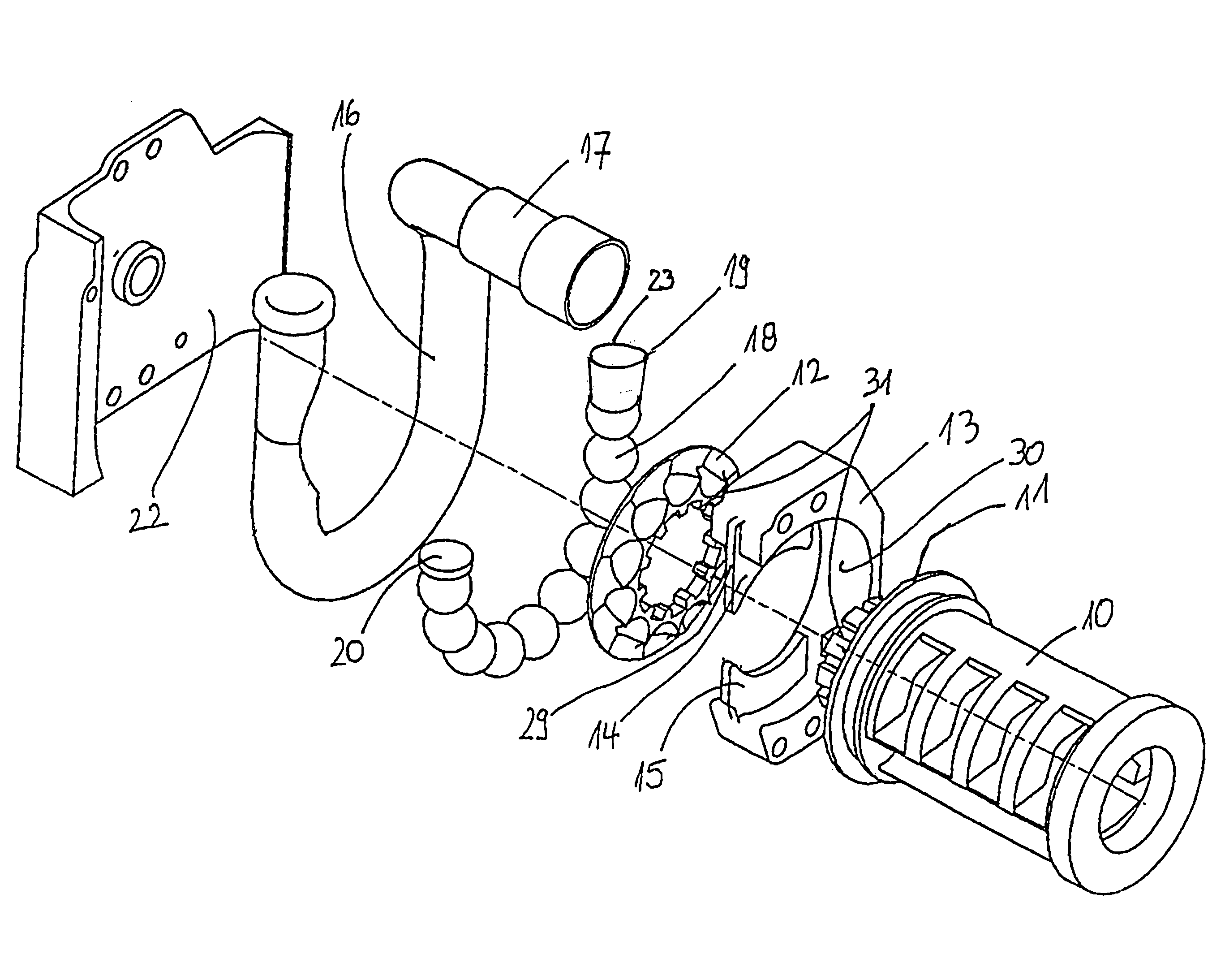
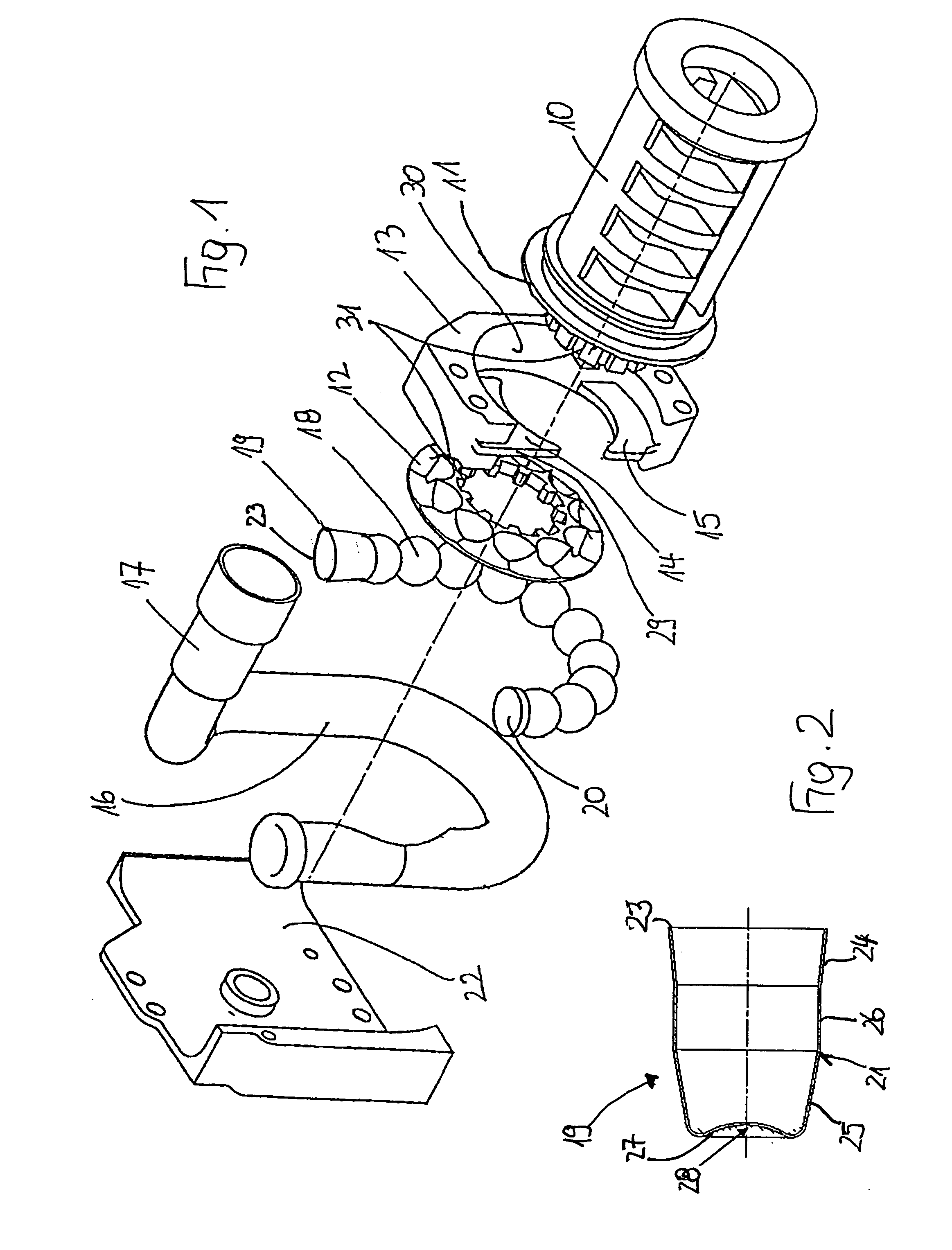
[0014]As is not further shown in detail, a belt rewinding shaft (or spool) 10 is rotatably mounted in a normally U-shaped and load-bearing belt retractor housing. In order to set the belt rewinding shaft 10 into a rotation tightening the belt wound around it, a pyrotechnic drive is provided that consists of both first and second drive wheel halves 11 and 12, whereby the first drive wheel half 11 is firmly connected to the belt rewinding shaft 10 in the embodiment represented. As is apparent from FIG. 1, on assembly of the rotary tightening device, the second drive wheel half 12 is mounted against the first drive wheel half 11 and connected thereto by means of a gear 31. A casing 13 which is part of the housing of the belt retractor is arranged between both drive wheel halves 11 and 12, which in the meantime bears the tongue-shaped channels 14, 15 reaching in-between both drive wheel halves 11 and 12 and encloses the outer volume of the drive wheel halves 11 and 12 with its inner vol...


PUM


Abstract

A belt pretensioner for safety belts, in particular in motor vehicles, with a pretensioner drive which, in the event it is triggered, can be coupled to the belt shaft, and includes a drive wheel which is enclosed over at least part of its volume by a tubular housing which forms a channel in its interior, whereby, in order to drive the drive wheel, a plurality of solid balls, which are accelerated by means of a pyrotechnic drive, can be guided through the channel, and a drive piston for the solid balls is arranged at that end of the channel which is to be acted upon by the gas introduced, characterized in that the drive piston (19) is designed in the manner of a hollow cup and, on its closed end side (27), is provided with an inwardly directed curvature (28) adapted to the contour of a solid ball (18).

Description

CROSS REFERENCE TO RELATED APPLICATION[0001]This application claims priority to International Application No. PCT / EP2008 / 004644, filed Jun. 11, 2008, which is based on and claims priority to German Patent Application No. 10 2007 028 980.6, filed Jun. 23, 2007.FIELD OF THE INVENTION[0002]The present invention relates to a seat belt tightener or pretentioner for safety belts, in particular in motor vehicles.BACKGROUND OF THE INVENTION[0003]The pretensioner in accordance with this invention includes a pretensioner drive which, in the event it is triggered, can be coupled to the belt retractor shaft, and which includes a drive wheel which is enclosed over at least part of its volume by a tubular housing which forms a channel in its interior, whereby, in order to drive the drive wheel, a plurality of solid balls, which, accelerated by means of a pyrotechnic drive, can be guided through the channel, and a drive piston for the solid balls is arranged at that end of the channel which is to ...

Claims


Application Information

Patent Timeline
Patent Type & Authority Applications(United States)
IPC IPC(8): B60R22/46
CPCB60R2022/4642B60R22/4628
Inventor SUHR, STEFANFREY, ERNESCHMIDT, MARTIN
Owner AUTOLIV DEV AB
Why Eureka
Try Eureka