Resistive touch control device and driving method and driving controller thereof
a technology of resistive touch control and driving controller, which is applied in the direction of instruments, computing, electric digital data processing, etc., can solve the problem that the capacitive touch panel cannot be operated by a glove-covered finger or a non-conductive medium
- Summary
- Abstract
- Description
- Claims
- Application Information
AI Technical Summary
Benefits of technology
Problems solved by technology
Method used
Image
Examples
first embodiment
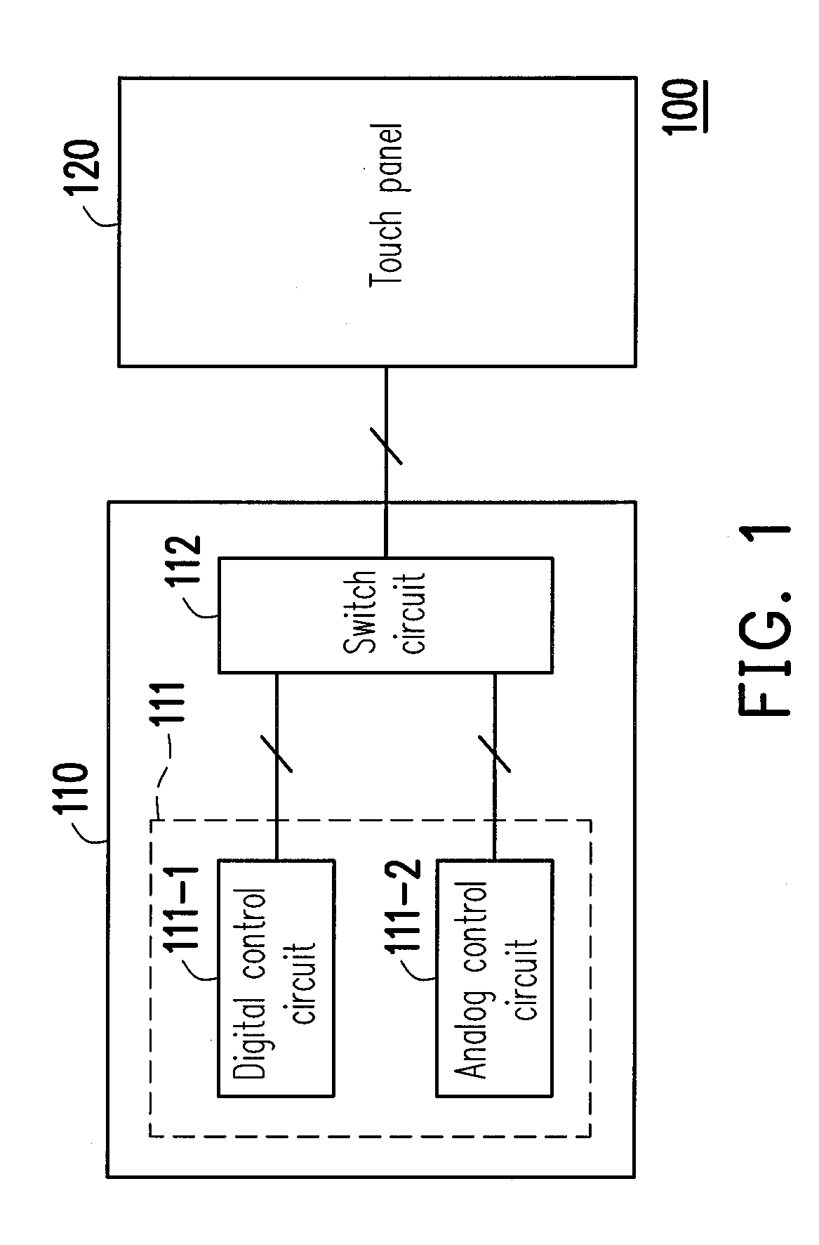
[0036]In the first embodiment, before the touch control device 100 is used, the user can select to switch the touch control device 100 to a digital mode or an analog mode according to an actual requirement. Then, the control module 111 sends a control signal (not shown) to the switch circuit 112 according to the user's selection, so that the switch circuit 112 can couple the touch panel 120 to the digital control circuit 111-1 or the analog control circuit 111-2 according to the control signal sent from the control module 111, and therefore the touch control device 100 can be operated in the digital mode or the analog mode. In other words, based on the switch circuit 112, the user can select to determine the touched sensing blocks of the touch panel 120 through the digital control circuit 111-1 or to obtain the touch coordinates (i.e. a touched position) through the analog control circuit 112-2.
[0037]To fully describe that how the switch circuit 112 switches such two operation modes...
second embodiment
[0046]The present invention further provides another switch circuit to achieve a different switching method. FIG. 5 is a schematic diagram illustrating a switch circuit 112 according to the second embodiment of the present invention. Referring to FIG. 1 and FIG. 5, the switch circuit 112 includes the switch group G1˜G4 and a selection circuit 513. The switch groups G1˜G4 includes a plurality of multiplexers 311˜318, and the selection circuit 513 includes a plurality of multiplexers 513-1˜513-4.
[0047]Similarly, the signal terminals of the multiplexers of the same switch group are coupled to the conductive electrodes located at a same side of the touch panel 120, and the switch groups (for example, the switch group G1 and the switch group G3) corresponding to different transparent conductive patterns of the touch panel 120 are coupled to the digital control circuit 111-1. In other words, the first mode terminals a1, a3, a5 and a7 of the multiplexers 311, 313, 315 and 317 are coupled t...
third embodiment
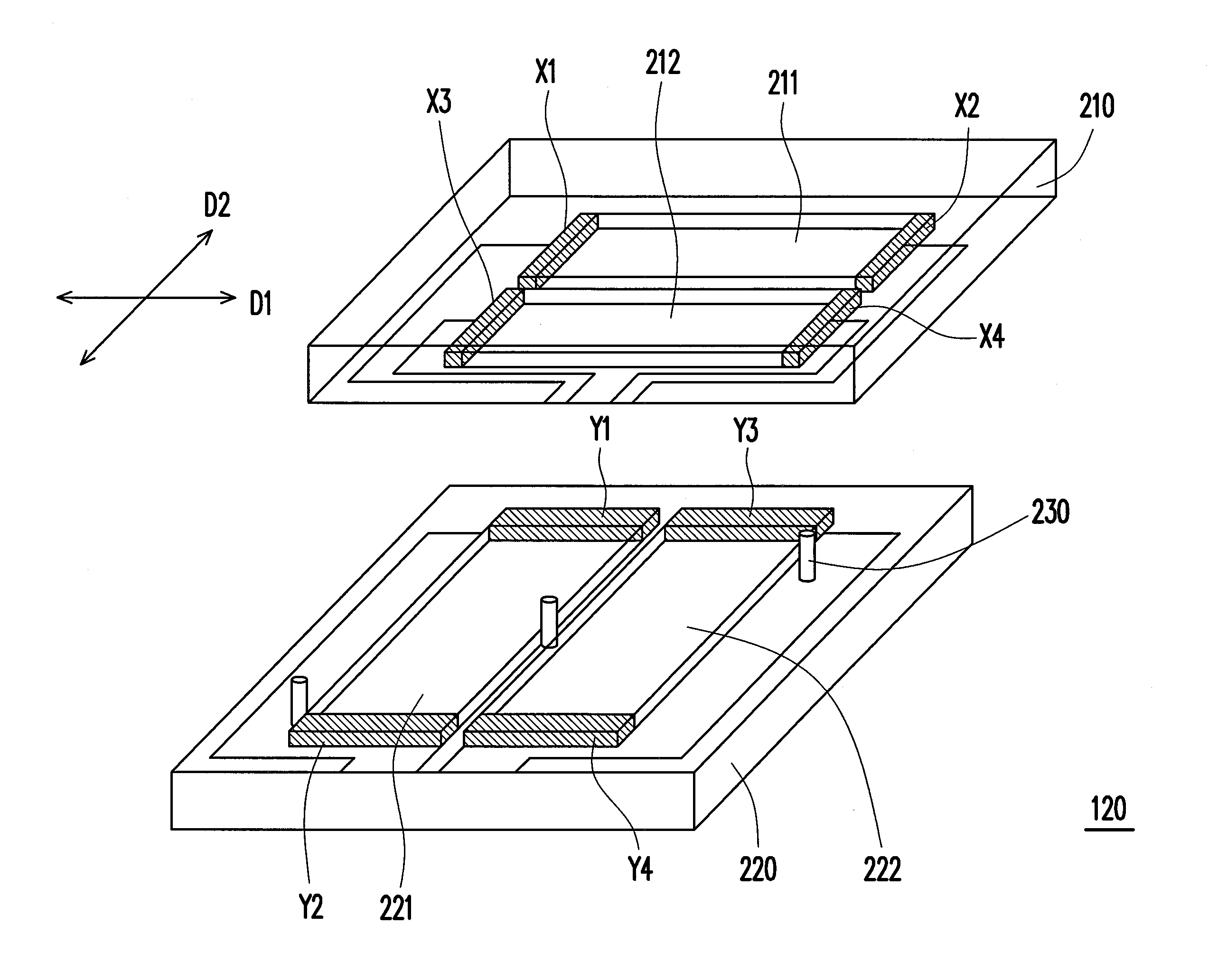
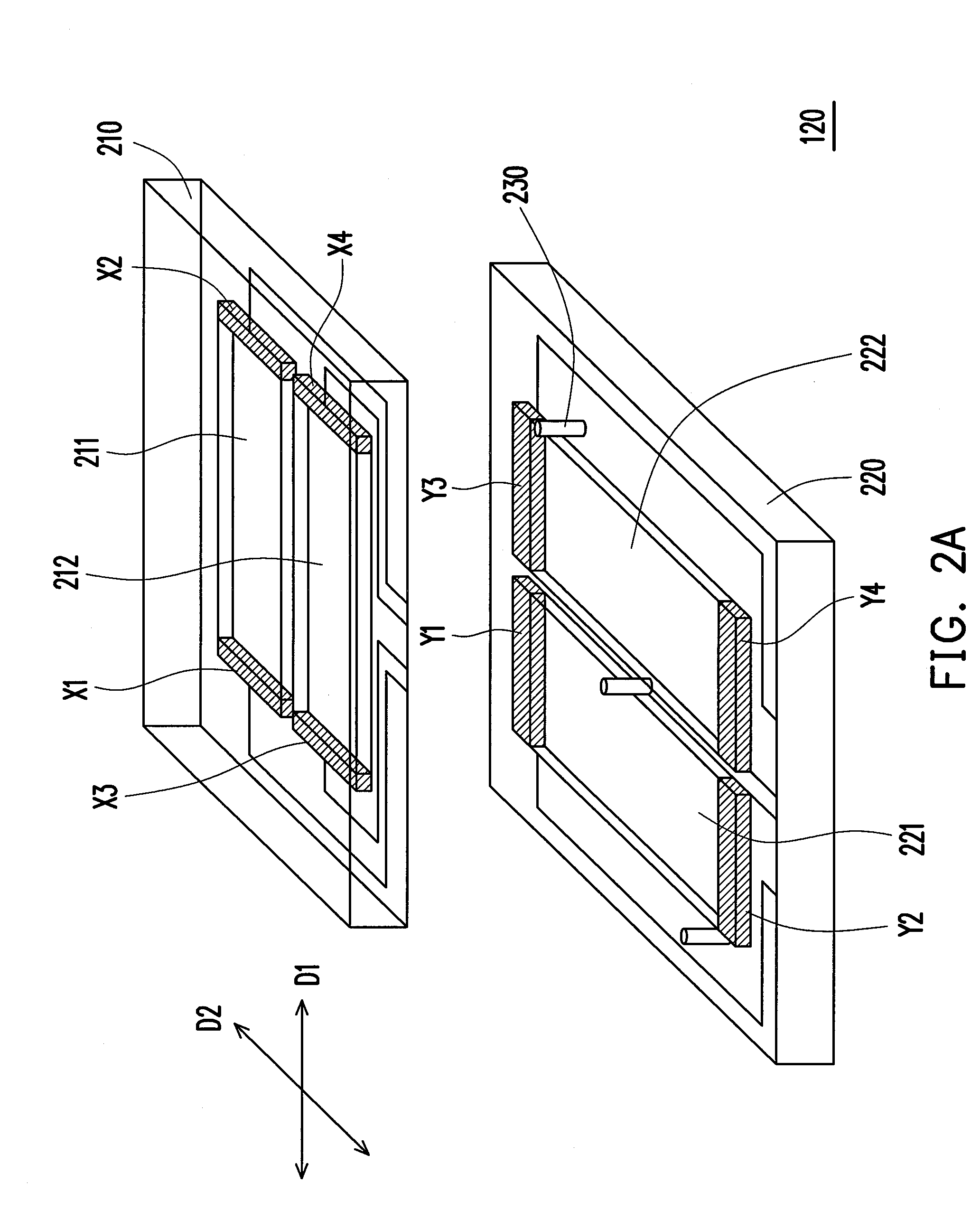
[0059]The transparent conductive patterns of a 3×3 array are taken as an example. FIG. 7 is a top view of a touch panel 700. Conducive patterns 711, 712, 713 are disposed on a transparent substrate 701, and are respectively extended along the direction D1 in parallel. Two ends of the conductive pattern 711 are coupled to conductive electrodes X10 and X11, two ends of the conductive pattern 712 are coupled to conductive electrodes X20 and X21, and two ends of the conductive pattern 713 are coupled to conductive electrodes X30 and X31. On the other hand, conductive patterns 721, 722, 723 are disposed on another transparent substrate (not shown), and are respectively extended along the direction D2 in parallel. Two ends of the conductive pattern 721 are coupled to conductive electrodes Y10 and Y11, two ends of the conductive pattern 722 are coupled to conductive electrodes Y20 and Y21, and two ends of the conductive pattern 723 are coupled to conductive electrodes Y30 and Y31. The dire...
PUM
 Abstract
Description
Claims
Application Information
 - R&D
- Intellectual Property
- Life Sciences
- Materials
- Tech Scout
- Unparalleled Data Quality
- Higher Quality Content
- 60% Fewer Hallucinations
Browse by: Latest US Patents, China's latest patents, Technical Efficacy Thesaurus, Application Domain, Technology Topic, Popular Technical Reports.
© 2025 PatSnap. All rights reserved.Legal|Privacy policy|Modern Slavery Act Transparency Statement|Sitemap|About US| Contact US: help@patsnap.com


