Method, system, and device of video communication

a video communication and video communication technology, applied in the field of communication technology, can solve the problems of insufficient flexibility and affect the reality sense of video communication, and achieve the effect of improving flexibility and reducing the close relationship between the mcu and the terminal

Active Publication Date: 2010-07-22
HUAWEI DEVICE CO LTD +1
View PDF9 Cites 22 Cited by
  • Summary
  • Abstract
  • Description
  • Claims
  • Application Information

AI Technical Summary

Problems solved by technology

This results in the mismatch between position information of the sound and the sub-picture, and thus affects the reality sense of video communication.
In this way, a relationship between the MCU and the terminals becomes too close, thus causing insufficient flexibility.

Method used


Image

  • Method, system, and device of video communication
  • Method, system, and device of video communication
  • Method, system, and device of video communication

Examples


first embodiment

[0040]FIG. 5 is a flow chart of a method according to the present invention.

[0041]In step 201, a sub-picture in a synthetic picture corresponding to each received audio stream is marked. The received audio streams and the synthetic picture are illustrated in the following.

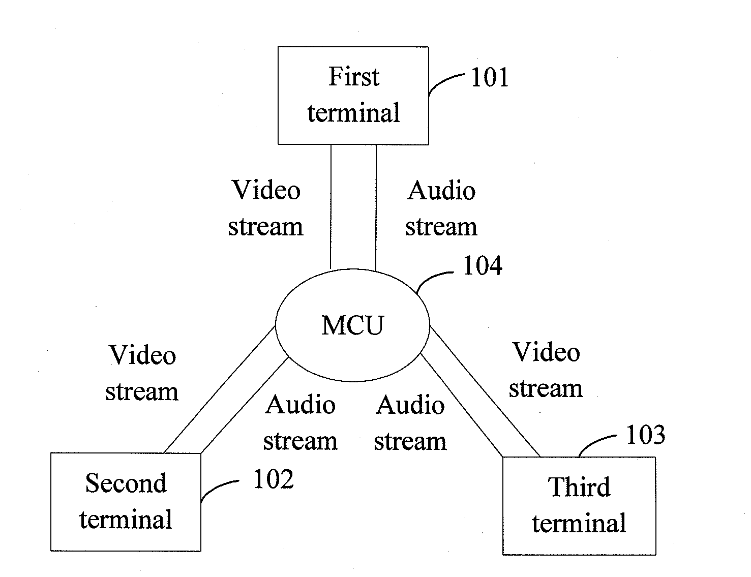
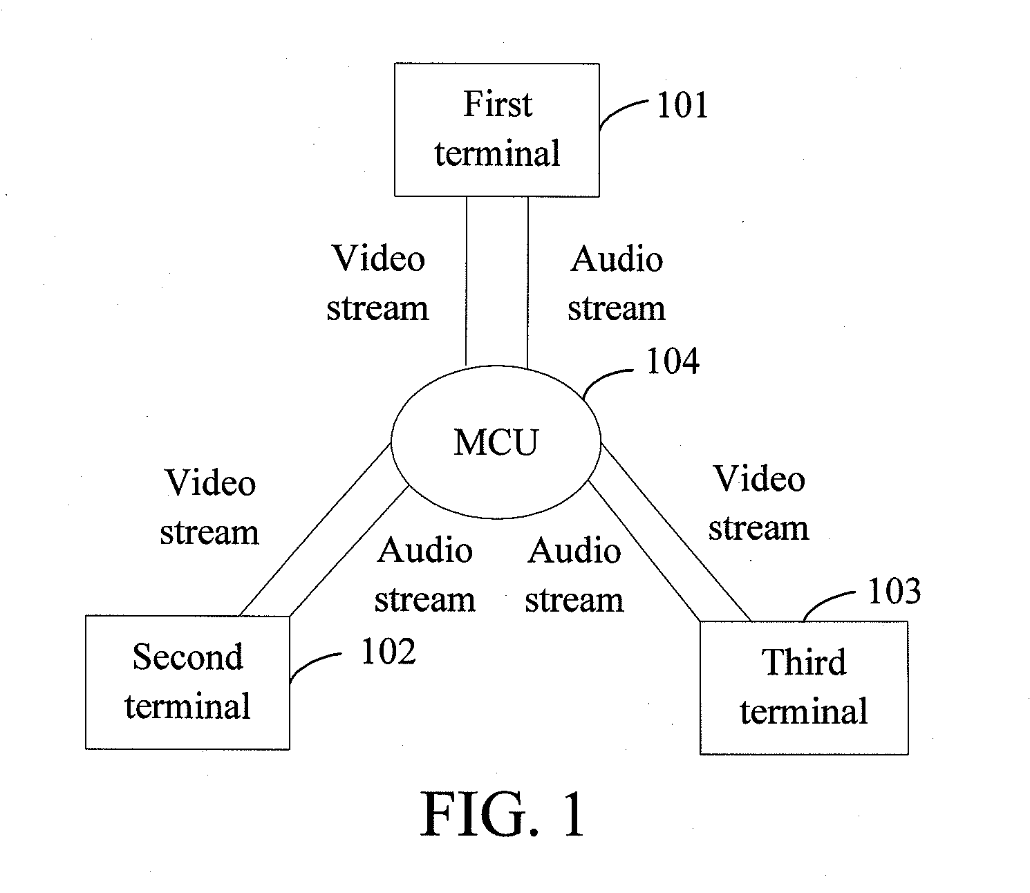
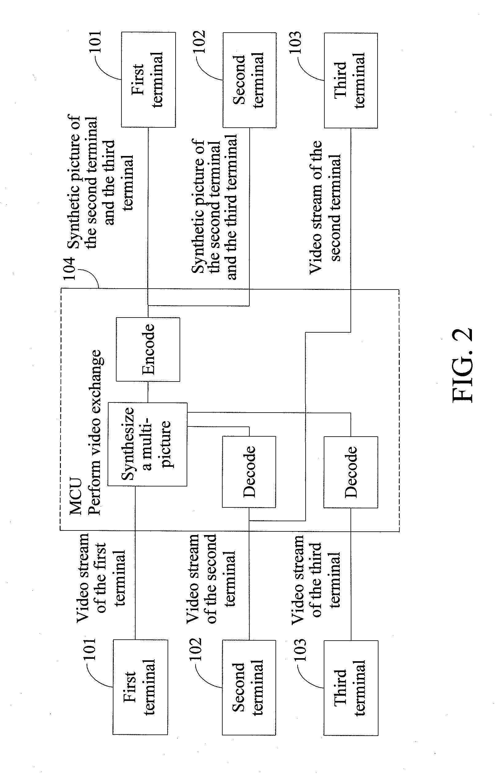
[0042]In Example 1, a video stream that the MCU sends to the first terminal is a synthetic picture of the second terminal and the third terminal, in which the second terminal is at a left sub-picture and the third terminal is at a right sub-picture. An audio stream that the MCU sends to the first terminal includes an audio stream of the second terminal and an audio stream of the third terminal, in which the audio stream for marking the second terminal corresponds to the left sub-picture and the audio stream of the third terminal corresponds to the right sub-picture. In Example 2, a video stream that the MCU sends to the second terminal is a synthetic picture of the second terminal and the third terminal. An audio s...

second embodiment

[0049]FIG. 6 is a flow chart of a method according to the present invention.

[0050]In step 301, a sub-picture in a synthetic picture corresponding to each received audio stream is marked. The received audio streams and the synthetic picture are demonstrated below by examples.

[0051]In Example 1, a video stream that the MCU sends to the first terminal is a synthetic picture of the second terminal and the third terminal, in which the second terminal is at a left sub-picture and the third terminal is at a right sub-picture. An audio stream that the MCU sends to the first terminal includes an audio stream of the second terminal and an audio stream of the third terminal, in which the audio stream for marking the second terminal corresponds to the left sub-picture and the audio stream of the third terminal corresponds to the right sub-picture. In Example 2, a video stream that the MCU sends to the second terminal is a synthetic picture of the second terminal and the third terminal. An audio...

third embodiment

[0059]FIG. 7 is a flow chart of a method according to the present invention.

[0060]In step 401, a sub-picture in a synthetic picture corresponding to each received audio stream is marked. The received audio streams and the synthetic picture are demonstrated below by examples.

[0061]In Example 1, a video stream that the MCU sends to the first terminal is a synthetic picture of the second terminal and the third terminal, in which the second terminal is at a left sub-picture and the third terminal is at a right sub-picture. An audio stream that the MCU sends to the first terminal includes an audio stream of the second terminal and an audio stream of the third terminal, in which the audio stream for marking the second terminal corresponds to the left sub-picture and the audio stream of the third terminal corresponds to the right sub-picture. In Example 2, a video stream that the MCU sends to the second terminal is a synthetic picture of the second terminal and the third terminal. An audio...


PUM


Abstract

A method, a system, and a device of video communication are provided. A sub-picture in a synthetic picture corresponding to each audio stream received is marked. Position information of each audio stream is obtained according to a position of each sub-picture in the synthetic picture. The audio stream and the corresponding position information are sent to a terminal. The terminal processes an audio signal according to the received position information of the audio stream, so that the audio stream carries the position information. During the video communication, the terminal receives the audio stream and the position information, and performs position information sense processing to the audio stream according to the position information. This reduces the frequent communication between the terminal and a device for processing position information and improves the flexibility of the system.

Description

CROSS-REFERENCE TO RELATED APPLICATIONS[0001]This application is a continuation of International Application No. PCT / CN2008 / 072483, filed on Sep. 24, 2008, which claims priority to Chinese Patent Application No. 200710151406.X, filed on Sep. 28, 2007, both of which are hereby incorporated by reference in their entireties.FIELD OF THE TECHNOLOGY[0002]The present invention relates to the field of communications technology, and more particularly to a method, a system, and a device of video communication.BACKGROUND OF THE INVENTION[0003]With the popularity of televisions, users have increasingly high requirements for a size of a television screen. Some video communication systems even adopt a projector or a television wall for displaying. In this case, if one picture is synthesized by at least two sub-pictures, positions of speakers in different sub-pictures are quite different when the requirements for a screen size are low. However, in a current multimedia communication system, positi...

Claims


Application Information

Patent Timeline
Patent Type & Authority Applications(United States)
IPC IPC(8): H04N7/14
CPCH04N7/152
Inventor ZHAN, WUZHOU
Owner HUAWEI DEVICE CO LTD
Why Eureka
Try Eureka