Low stray light veiling glare objective lens for night vision systems

a technology of objective lens and stray light, which is applied in the field of low stray light veiling glare objective lens for night vision systems, can solve the problems of manifested veiling glare, and achieve the effects of reducing glare, reducing glare to the viewer, and less veiling glar

Inactive Publication Date: 2010-07-22
EXCELIS INC
View PDF9 Cites 12 Cited by
  • Summary
  • Abstract
  • Description
  • Claims
  • Application Information

AI Technical Summary

Benefits of technology

[0005]Light traps may be disposed adjacent to the lens. The peripheral edge of the lens is configured to direct light that is received from the object toward the light traps. Since the light at the periphery of the lens is directed toward the light traps, less veiling glare is seen by the viewer.
[0006]The present invention further provides a lens assembly. The lens assembly includes a plurality of lenses disposed along an optical axis. Each lens includes first and second surfaces extending radially from the optical axis for passing light from an object to a viewer. Each lens includes a peripheral edge extending between respective first and second surfaces. A peripheral edge of at least one of the lenses includes a portion having either a positive slope or a negative slope with respect to the optical axis. The positive or negative slope of the peripheral edge is configured to reduce glare to stray light received from the first surface and transmitted toward the second surface of the one lens.
[0007]A portion of the peripheral light may be trapped by light traps that are disposed adjacent to some of the lenses. The positive or negative slope of the peripheral edges of the lenses are configured to direct the peripheral light toward the light traps and be captured therein, thereby reducing glare to the viewer.

Problems solved by technology

Veiling glare is a defect manifested by visible areas of light that are disposed outside a field of view of an optical system, when the optical system views a scene having a bright source of light.

Method used


Image

  • Low stray light veiling glare objective lens for night vision systems
  • Low stray light veiling glare objective lens for night vision systems
  • Low stray light veiling glare objective lens for night vision systems

Examples


Embodiment Construction

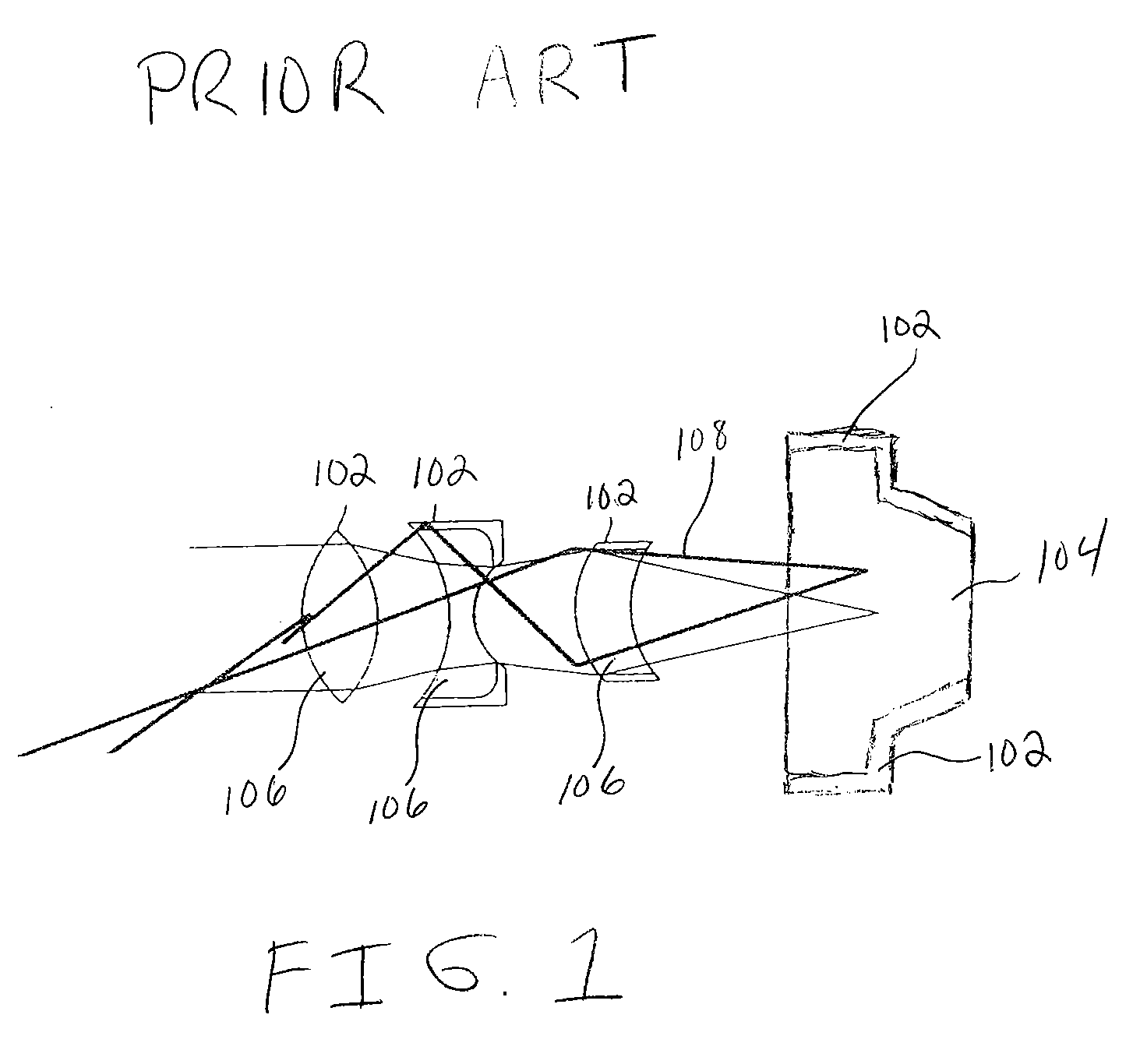
[0019]The “blackened” edges described in conventional systems are partially absorbent and scatter any unabsorbed light into the field of view of the lens system causing veiling glare. FIG. 1 shows different prior art lenses 106 including face plate 104 having blackened edges 102. While edges 102 are blackened with an absorbing ink, light energy may not be effectively absorbed by the ink. As shown in FIG. 1, light energy 108 reflects off from blackened edges 102, causing veiling glare.

[0020]Hydrogen firing of lenses for veiling glare reduction may absorb additional light energy. Unfortunately, the types of glass which may be selected for hydrogen firing are limited. Furthermore, the edges of lenses that are hydrogen fired to form blackened surfaces having the same index of refraction require additional processing and edge grinding.

[0021]Although hydrogen fired blackened edges may absorb large amounts of light in the blue, green and red spectral regions, these edges are transmissive i...


PUM


Abstract

A lens includes first and second opposing surfaces extending radially from an optical axis in an optical system for passing light received from an object. The lens includes a peripheral edge extending between the first and second surfaces. A portion of the peripheral edge has at least either a positive slope or a negative slope with respect to the optical axis. The positive or negative slope of the peripheral edge is configured to reduce glare from stray light received from the first surface. A portion of the peripheral edge may be shaped in a sawtooth pattern or an approximate sinusoidal pattern. The peripheral edge of the lens is also configured to direct light that is received from the object toward light traps which are disposed adjacent to the lens.

Description

BACKGROUND OF THE INVENTION[0001]Veiling glare is a defect manifested by visible areas of light that are disposed outside a field of view of an optical system, when the optical system views a scene having a bright source of light. Veiling glare is distinguished from ghost images, the latter having flares or arcs of light that are disposed inside the field of view of the optical system, due to viewing bright sources.[0002]Night vision goggle systems typically include an amplifier which detects an image from an objective lens and amplifies the image prior to viewing. Veiling glare, caused by reflections from the lens mounting system, lens edges and lens surfaces, may also be amplified prior to viewing, masking real targets and objects having an output signal smaller than the veiling glare signal.[0003]Conventional veiling glare mitigation techniques in night vision systems include “blackening” edges of lens elements in the objective lens with ink or paint. For example, U.S. Pat. No. 4...

Claims


Application Information

Patent Timeline
Patent Type & Authority Applications(United States)
IPC IPC(8): G02B3/00
CPCG02B5/003G02B27/0018G02B23/12
Inventor THOMAS, NILS I.DOSHI, REKHAJANECZKO, DONALD J.
Owner EXCELIS INC
Why Eureka
Try Eureka