Standby power saving system and computer power-on and power-off method thereof

a technology of standby power and power saving system, which is applied in the direction of liquid/fluent solid measurement, instruments, high-level techniques, etc., can solve the problems of reducing the standby power of peripheral apparatuses, unable to save and still power consumption, so as to reduce the consumed standby power

Inactive Publication Date: 2010-07-22
DELTA ELECTRONICS INC
View PDF6 Cites 13 Cited by
  • Summary
  • Abstract
  • Description
  • Claims
  • Application Information

AI Technical Summary

Benefits of technology

[0007]It is an object of the present invention to provide a standby power saving system for monitoring the conditions of the computer, the monitor and the at least one peripheral apparatus, wherein the AC powers of the computer, the monitor and the peripheral apparatus is cut off according to the monitoring result or a command of a user, thereby reducing the consumed standby power.
[0013]To sum up, by monitoring the conditions of the computer and the peripheral apparatus connected to the computer, when the computer and the peripheral apparatus are in a standby state for a predetermined period of time, the AC powers of the computer and the peripheral apparatus are turned off, thereby reducing the consumed standby-power of the computer and the peripheral apparatus.

Problems solved by technology

However, when the computer shuts down and the AC power lines of the computer and its related peripheral apparatuses are still not removed from the sockets, there is still power consumed.
It cannot save the consumed standby power when the computer is in a power-off state.
However, it only eliminates the standby power of the peripheral apparatuses because the power of the computer must be detected.
Therefore, the standby power of the computer cannot be saved.
It is not favorable for the user.
Moreover, when the computer and the peripheral apparatuses are in a power-on state, the power-saving socket cannot save the standby powers of those peripheral apparatuses.

Method used


Image

  • Standby power saving system and computer power-on and power-off method thereof
  • Standby power saving system and computer power-on and power-off method thereof
  • Standby power saving system and computer power-on and power-off method thereof

Examples


Embodiment Construction

[0020]The present invention will be apparent from the following detailed description, which proceeds with reference to the accompanying drawing.

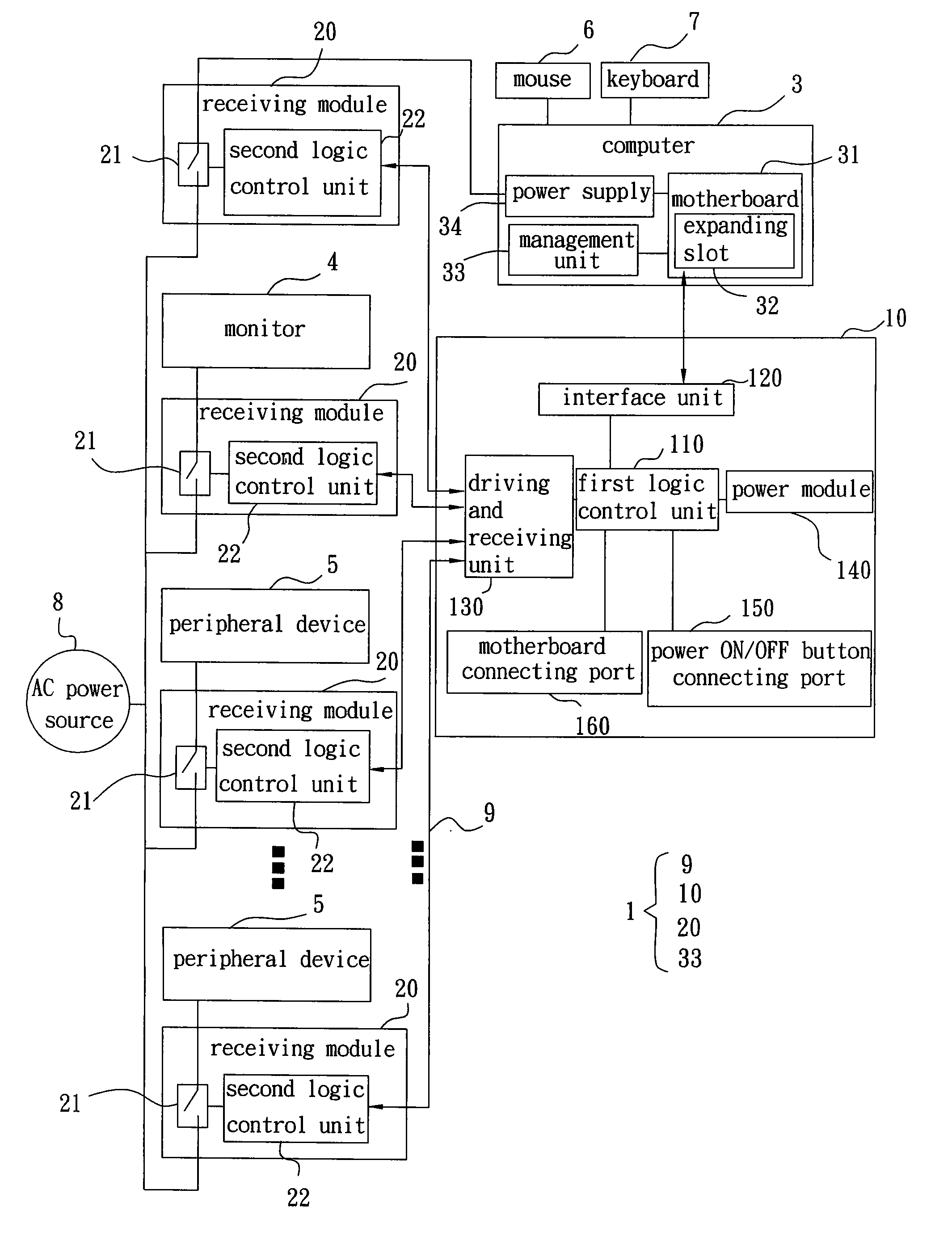
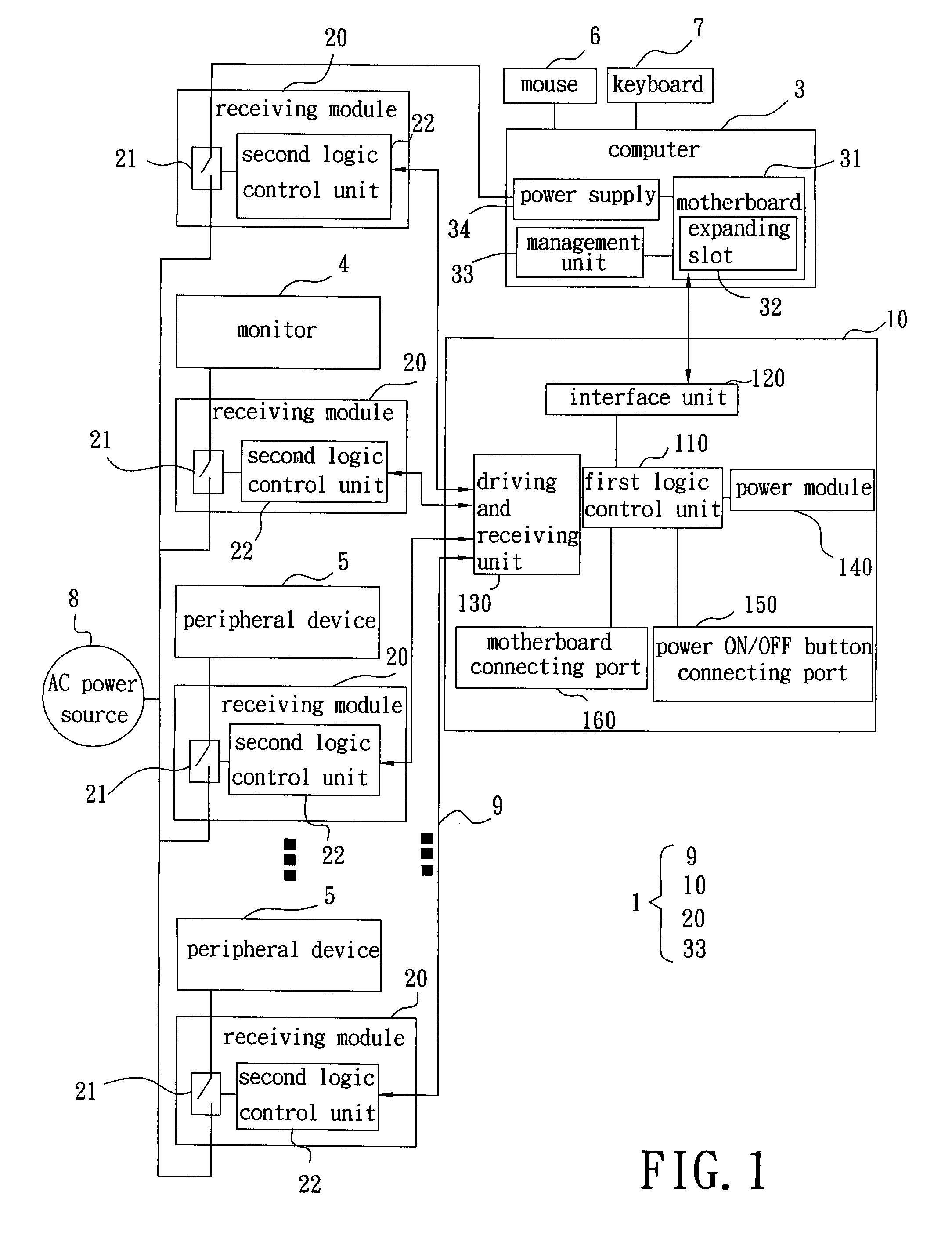
[0021]FIG. 1 is a block diagram illustrating a standby power saving system of the present invention. The standby power saving system 1 for cutting off or recovering the AC power of a computer 3, a monitor 4 and / or at least one peripheral apparatus 5 includes a standby power control module 10 and at least one receiving module 20.

[0022]The standby power control module 10 is connected to or disposed on a motherboard 31 of a computer 3 for bidirectional signal transmission and transmitting a control signal. The standby power control module 10 can be built on board and integrated onto the motherboard 31. Alternatively, the standby power control module 10 can be an interface card and inserted in an expanding slot 32 of the motherboard 31 for bidirectional signal transmission with the motherboard 31. The plurality of receiving module 20 are respect...


PUM


Abstract

A standby power saving system includes a standby power control module connected to or disposed on a motherboard of a computer for bidirectional signal transmission and transmitting a control signal; and at least one receiving module disposed on at least one AC power line of the computer and / or at least one peripheral apparatus, and connected to the standby power control module for receiving the control signal to switch on or off AC powers of the computer and / or the peripheral apparatus.

Description

CROSS REFERENCE TO RELATED APPLICATIONS[0001]This Non-provisional application claims priority under 35 U.S.C. §119(a) on Patent Application No(s). 098101853 filed in Taiwan, Republic of China on Jan. 19, 2009, the entire contents of which are hereby incorporated by reference.BACKGROUND OF THE INVENTION[0002]1. Field of Invention[0003]The present invention relates to a standby power saving system for monitoring the conditions of the computer, the monitor and the at least one peripheral apparatus, wherein the AC powers of the computer, the monitor and the peripheral apparatus are turned off according to the monitoring result or a command of a user, thereby reducing the consumed standby power.[0004]2. Related Art[0005]Depending on the power management function in the operating system, current desktop computers save the power by entering sleep mode or standby mode, etc, when the user doesn't operate the computer. However, when the computer shuts down and the AC power lines of the comput...

Claims


Application Information

Patent Timeline
Patent Type & Authority Applications(United States)
IPC IPC(8): G06F1/32
CPCG06F1/266Y02D50/20G06F1/325G06F1/3203Y02D30/50
Inventor CHEN, CHIEH-CHENGCHANG, CHIH-YUANCHIU, CHING-LIANG
Owner DELTA ELECTRONICS INC
Why Eureka
Try Eureka