
System for Quickly Specifying Formal Verification Environments

a formal verification and environment technology, applied in the field of computer aided design verification, can solve the problems of tedious and repetitive tasks, one of the most labor-intensive tasks in a formal verification project,

Active Publication Date: 2010-07-22
SIEMENS PROD LIFECYCLE MANAGEMENT SOFTWARE INC
View PDF6 Cites 13 Cited by
  • Summary
  • Abstract
  • Description
  • Claims
  • Application Information

AI Technical Summary

Problems solved by technology

However, due to the potential of formal verification to search a state space exhaustively, formal verification engineers must be careful to ensure that the verification of the design-under-test (DUT) deals only with legal inputs.
In either case, specifying the environment manually, even with the aid of one of the above-described alternatives, remains one of the most labor-intensive tasks in a formal verification project.
It is indeed a tedious and repetitive task.

Method used


Image

  • System for Quickly Specifying Formal Verification Environments
  • System for Quickly Specifying Formal Verification Environments
  • System for Quickly Specifying Formal Verification Environments

Examples


example

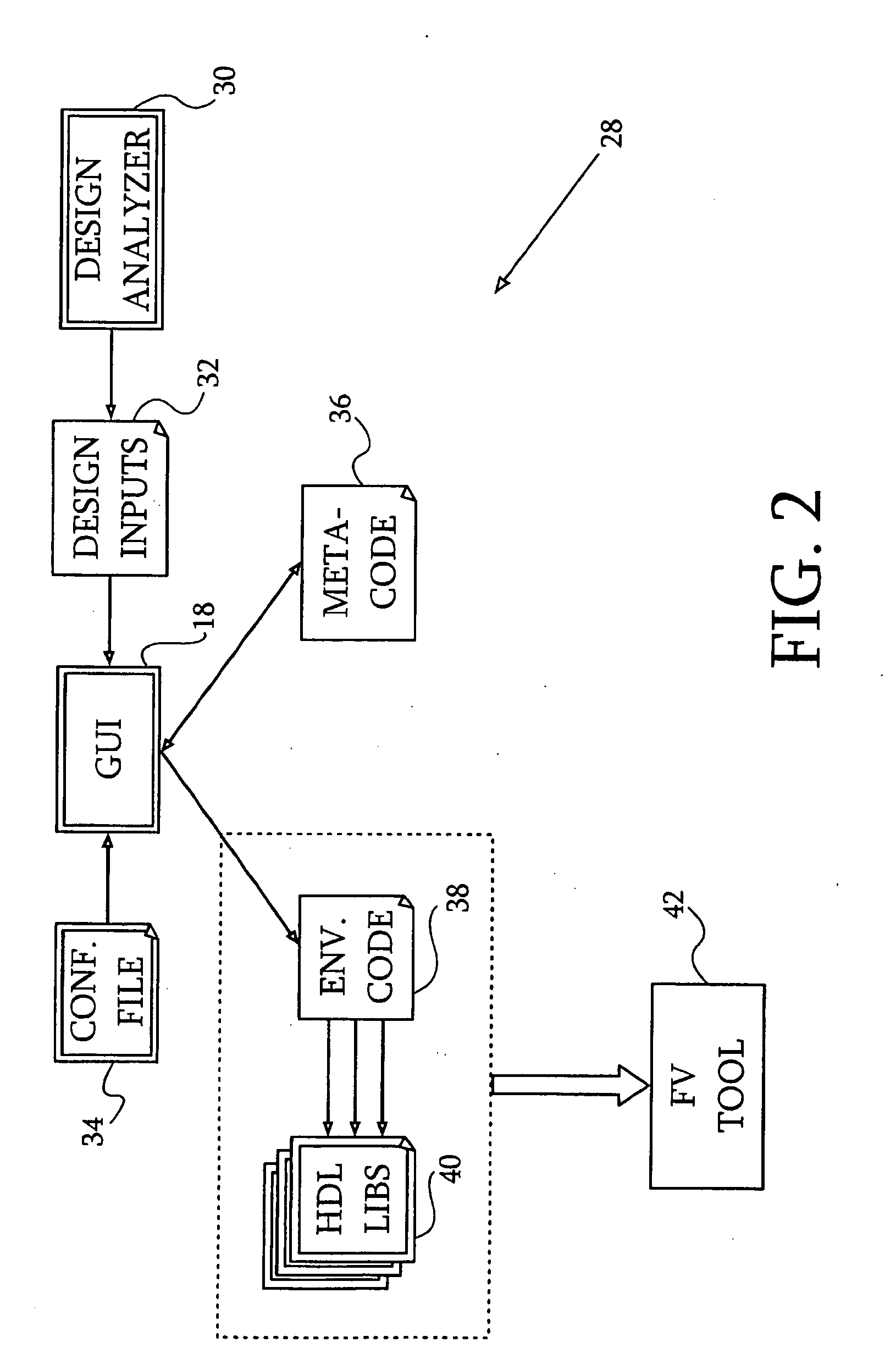
[0059]Reference is now made to FIG. 5, which is a screen display that is generated by environment wizard 28 (FIG. 2) via the graphical user interface 18, in accordance with a disclosed embodiment of the invention. A list of input signals appears in left pane 78. Assigned behaviors are displayed in central pane 80. Parameters for an assigned behavior appear in a lower right pane 82. In FIG. 5, a selected design signal “CLK” is assigned with a behavior called “Clock”, where the parameters are: (1) “clock type” having a value “toggling”; (2) “initial value” set to “0”; and (3) “period” set to “1”.

[0060]Reference is now made to FIG. 6, which is another screen display similar to FIG. 5 that is generated by environment wizard 28, in accordance with a disclosed embodiment of the invention. The display indicates assignment of a behavior to a signal called “DI[0:31]” (which is an array of 32 bits). Its assigned behavior is called “Counter” and the parameters appear on the right side of the d...

embodiment 1

Alternate Embodiment 1

[0062]From time to time the user may need to override the behavior options of an internal design signal that is available in the graphical user interface or a previously assigned behavior in order to assign a new (usually much simpler) behavior. The graphical user interface 18 may be modified to allow this by enabling the design analyzer to introduce an additional user-defined list of internal design signals and parameters for the design-under-test, for example, by reading an auxiliary configuration file. The graphical user interface may then present the additional list and allow the user to select a user-defined behavior rather than limiting him to one of the standard options.

embodiment 2

Alternate Embodiment 2

[0063]In this embodiment, the graphical user interface may suggest context-sensitive default parameter values, rather than pre-configured values from a configuration file. For example, when assigning a counter behavior to an input bus, the maximal counter value shown as a default in the graphical user interface may be 15 if the input being assigned applies to a Obit bus and 255 for an 8-bit bus. In another example when a particular input has been defined by the user as a clock, that input would be suggested as the clock port by the graphical user interface when defining the behavior of other inputs.


PUM


Abstract

Computer-implemented techniques are disclosed for defining an environment for formal verification of a design-under-test. Initially there is extraction of design inputs by a design analysis module, and presentation of the inputs on a graphical user interface. Behavior options for the design inputs are offered on the graphical user interface for selection by an operator. Environment code that is descriptive of the design inputs and selected behavior options is emitted, typically in a hardware description language, for submission to a formal verification tool. A meta-code file containing the assigned behavior options is generated to aid subsequent sessions.

Description

BACKGROUND OF THE INVENTION[0001]1. Field of the Invention[0002]This invention relates to computer aided design verification. More particularly, this invention relates to graphical techniques for explicitly assigning behaviors to hardware design inputs.[0003]2. Description of the Related ArtTABLE 1Acronyms and AbbreviationsDFTDesign-For-TestDUTDesign-Under-TestFVFormal VerificationHDLHardware Description LanguagePSLProperty Specification LanguageRAMRandom Access MemoryRTLRegister Transfer LevelVHDLVHSIC Hardware Description LanguageVHSICVery High Speed Integrated CircuitsXMLeXtensible Markup Language[0004]Formal verification (FV) has gained momentum in recent years and is now an important step in the process of validating a hardware design. For example, formal verification can pinpoint corner-case misbehaviors in a search space. However, due to the potential of formal verification to search a state space exhaustively, formal verification engineers must be careful to ensure that the ...

Claims


Application Information

Patent Timeline
IPC IPC(8): G06F17/50G06F19/00G06F3/048
CPCG06F8/34
Inventor AUERBACH, GADIELGAL, MATANNEVO, ZIV
Owner SIEMENS PROD LIFECYCLE MANAGEMENT SOFTWARE INC
Learn More