
System for flat-roof installation of solar modules

a solar module and installation system technology, applied in the direction of solar heat collector mounting/support, photovoltaics, etc., can solve the problems of expensive sealing measures at the penetration points, and the function of the watertight roof element is reduced

Inactive Publication Date: 2010-07-29
ENERGIETECHN VERW
View PDF12 Cites 19 Cited by
  • Summary
  • Abstract
  • Description
  • Claims
  • Application Information

AI Technical Summary

Benefits of technology

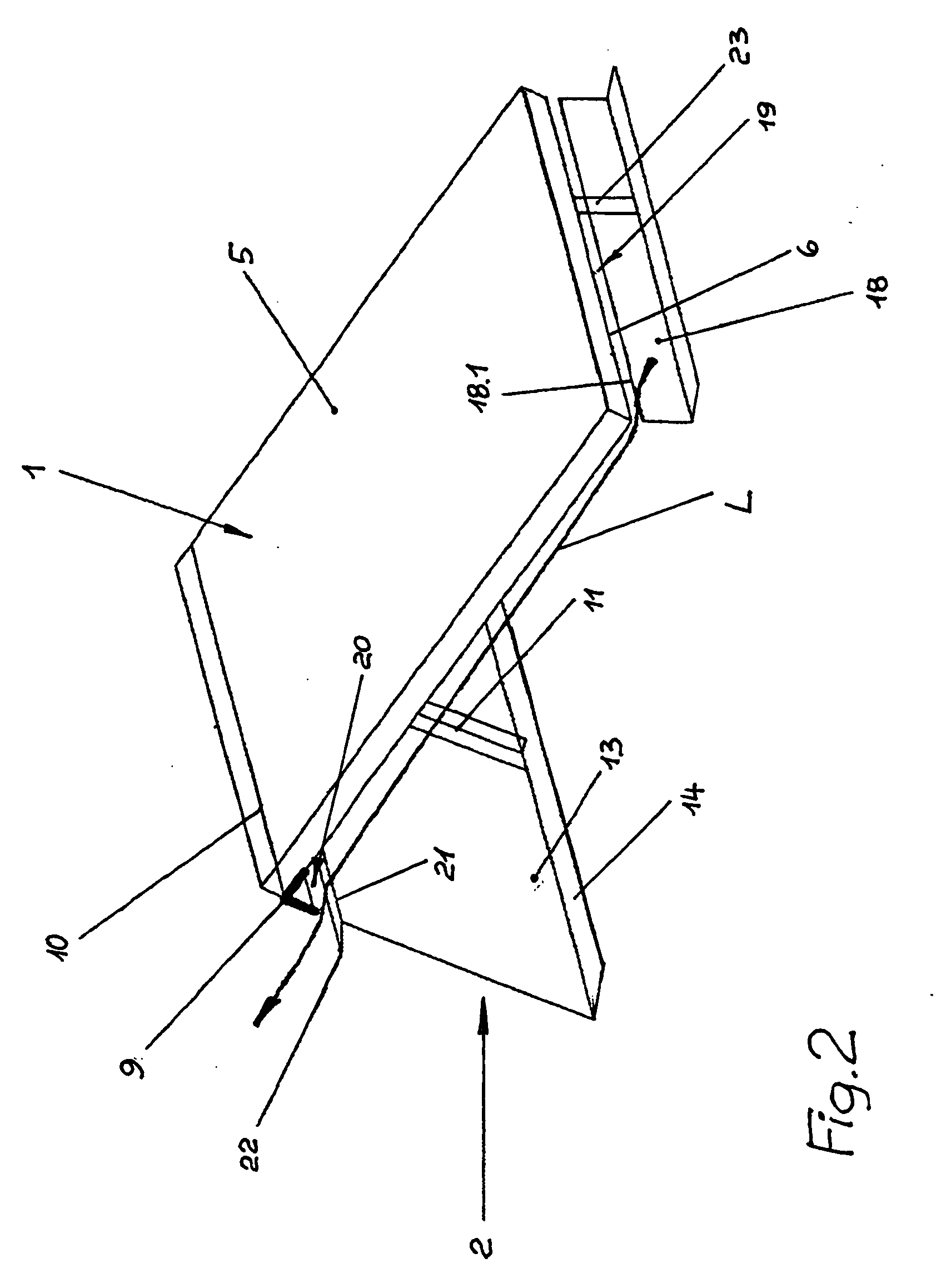
[0007]Thus, the roof installation set is essentially sucked downward onto the roof surface, and the pressure forces arising therefrom in the area of the bearing surfaces of the carrier help prevent the roof installation set from being displaced, overturned, or raised because of the friction created. The aerodynamic effect used here assumes that the area of the roof surface enclosing the roof installation set on its underside is correspondingly made to be windproof and airtight, which is not a problem because of the required water tightness of the roof surface.

Problems solved by technology

The supports required on the carrier penetrate the roof surface, which reduces its function as a watertight roof element.
In order to compensate for this, expensive sealing measures must be employed at the penetration points.

Method used


Image

  • System for flat-roof installation of solar modules
  • System for flat-roof installation of solar modules
  • System for flat-roof installation of solar modules

Examples


Embodiment Construction

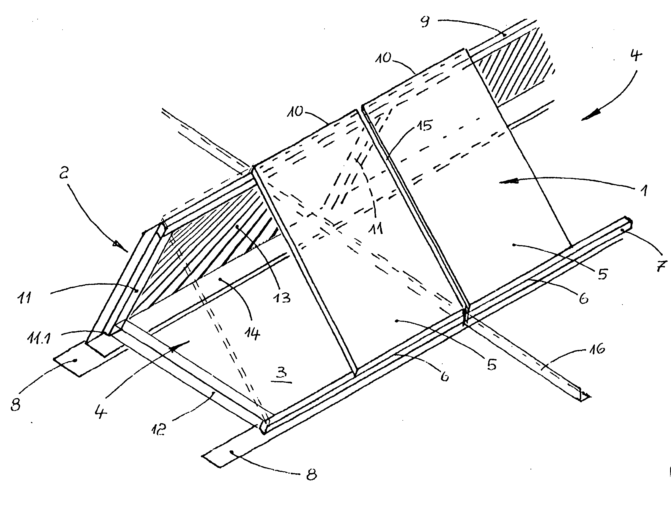
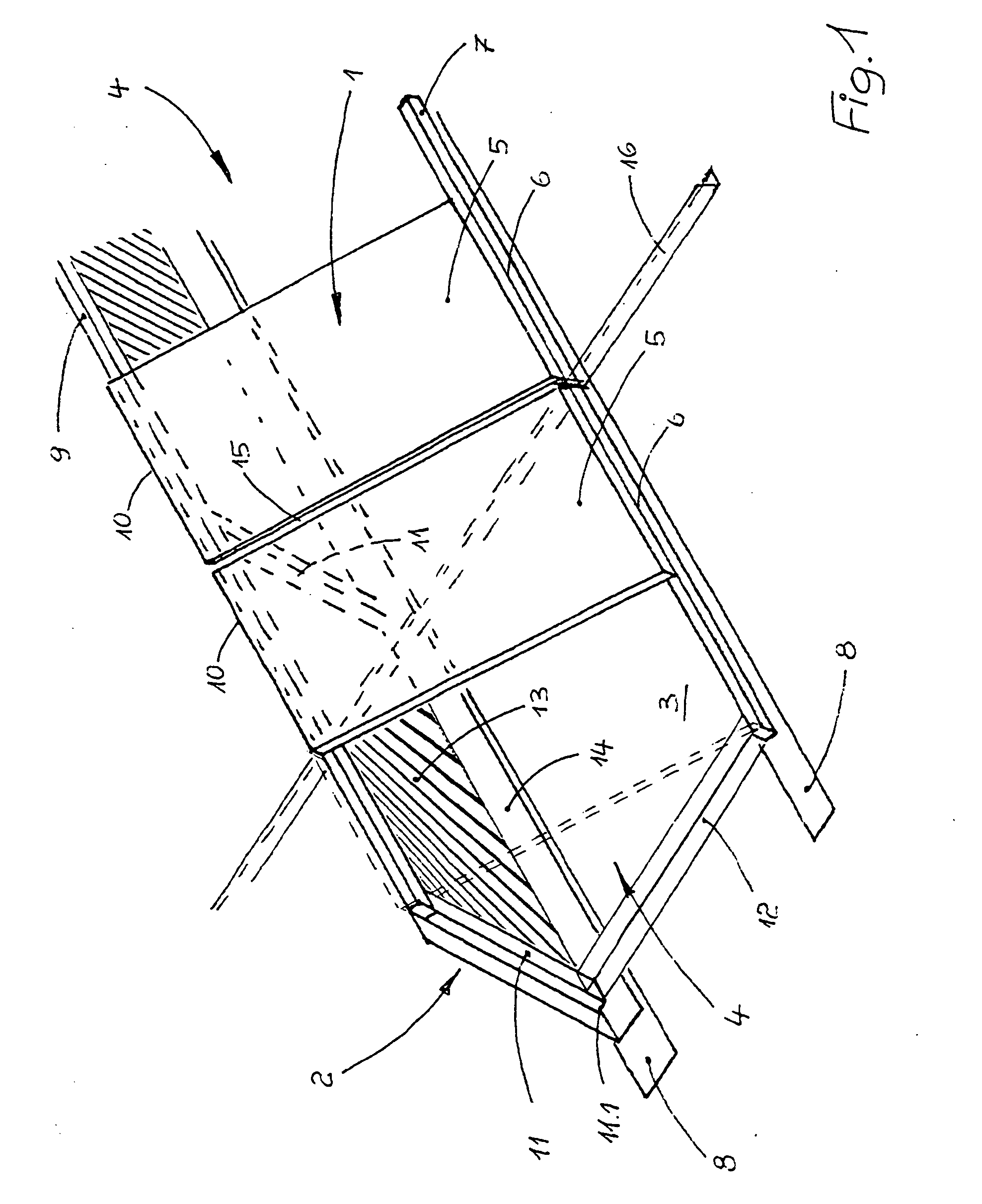
[0011]Specifically, one may recognize in FIG. 1 a solar module flat-roof installation set that has the shape of an acutely-angled or right-angled ridge roof. Thus, the flat-roof installation set possesses a first side 1, a second 2 positioned at an acute or right angle with respect to the first side 1, and face sides or end regions 4 open at both ends. When in operating position, the open underside of the flat-roof installation set is closed by the roof surface 3 that is correspondingly watertight and also airtight.

[0012]The first side 1 of the flat-roof installation set is provided with solar modules 5 that possess the shape of rectangular or square panels mounted in a common plane inclined relative to the roof surface 3. The solar modules 5 are a component of a photo-voltaic system, and generally are mounted in some quantity adjacent to one another as is known in the art of photo-voltaic systems. For this, the lower edges 6 and the upper edges 10 of the solar modules 5 are aligned...


PUM


Abstract

A flat-roof installation set for solar collector modules (5) includes a carrier frame on which the solar collector modules (5) are mounted, whereby the solar modules (5) are mounted on a first side of an installation set (1) adjacent to one another in a plane inclined from the roof surface (3) and with their upper and lower edges (6, 10) positioned in parallel to the roof surface (3) and aligned with one another. In order to compensate for wind loads using aerodynamic supports, a wind-suppressing or wind-blocking connector is provided between the lower edges (6) of the solar module (5) and the roof surface (3), and the second side of the installation set (2) between the upper edges of the solar modules and the roof surface (3) is implemented to be of enclosed design, and is inclined with respect to the solar modules (5) and opposite them. Both ends of the installation set (4) and the underside of the installation set are open to the roof surface (3).

Description

TECHNICAL FIELD[0001]The invention relates to a system for installing solar energy collector modules in a flat-roof installation.BACKGROUND INFORMATION[0002]Such a roof installation set is known from the patent document DE 10 2005 033 780 A1. In order to secure the roof installation set against wind loads, the carrier is anchored to a proper load-bearing sub-frame of the roof. The supports required on the carrier penetrate the roof surface, which reduces its function as a watertight roof element. In order to compensate for this, expensive sealing measures must be employed at the penetration points.[0003]Further, flat-roof installation sets with carriers are known that are merely placed on the roof surface of the flat-roof with friction mounts, i.e., they avoid the anchoring elements penetrating the roof surface. Stability against wind loads is provided by their substantial weight, for which the frame components themselves may be of heavy-weight construction as may be taken from the ...

Claims


Application Information

Patent Timeline
Patent Type & Authority Applications(United States)
IPC IPC(8): E04D13/18
CPCF24J2/4638F24J2/5233H02S20/24Y02B10/20Y02E10/47Y02B10/12F24S40/85F24S25/13Y02E10/50Y02B10/10
Inventor HOEFT, KLAUS-DIETERDUHAY, JOHANNESKEMPKENSTEFFEN, JOSEF
Owner ENERGIETECHN VERW
Learn More