
Beverage bottling plant for filling beverage bottles with a beverage bottle treatment machine and a beverage bottle treatment machine in a beverage bottling plant

a beverage bottling plant and beverage bottle technology, applied in packaging, food processing, climate change adaptation, etc., can solve the problems of limited transferable heat quantity, large structure of pasteurizing devices, and reduced end temperature at the outlet, so as to prevent overheating in the pasteurizing zone, and reduce the effect of overheating

Active Publication Date: 2010-07-29
KHS GMBH
View PDF6 Cites 6 Cited by
  • Summary
  • Abstract
  • Description
  • Claims
  • Application Information

AI Technical Summary

Benefits of technology

The present invention is a pasteurizing device for liquids in closed containers. The device has a heating zone, a pasteurizing zone, and a cooling zone, and uses an irrigation system to transfer heat from one segment to another. The device includes a heat pump and conveying units to circulate the liquid through the segments. The device can be controlled to regulate the temperature, and even in the event of damage or overheating, the device can still effectively and quickly recover. The invention provides a simple and effective solution for pasteurizing liquids in closed containers.

Problems solved by technology

As the temperature of the closed containers can be increased in a limited manner, the dwell time has to or should be increased, which means that the pasteurizing devices are structurally very large.
The problem of one possible process is that the pasteurizing devices have to be structurally very large to cool the pasteurized and filled containers in the desired recuperative manner; however, it is possible to achieve a cooling temperature that is a little above the temperature of the first heating segment.
A connection of this type may possibly reduce the end temperature at the outlet, however the transferable heat quantity is limited as the temperature of the liquid to be filled must or should not be increased in an arbitrary manner upstream of the filing process in order to prevent, restrict, and / or minimize, amongst other things, serious frothing.

Method used


Image

  • Beverage bottling plant for filling beverage bottles with a beverage bottle treatment machine and a beverage bottle treatment machine in a beverage bottling plant
  • Beverage bottling plant for filling beverage bottles with a beverage bottle treatment machine and a beverage bottle treatment machine in a beverage bottling plant
  • Beverage bottling plant for filling beverage bottles with a beverage bottle treatment machine and a beverage bottle treatment machine in a beverage bottling plant

Examples


Embodiment Construction

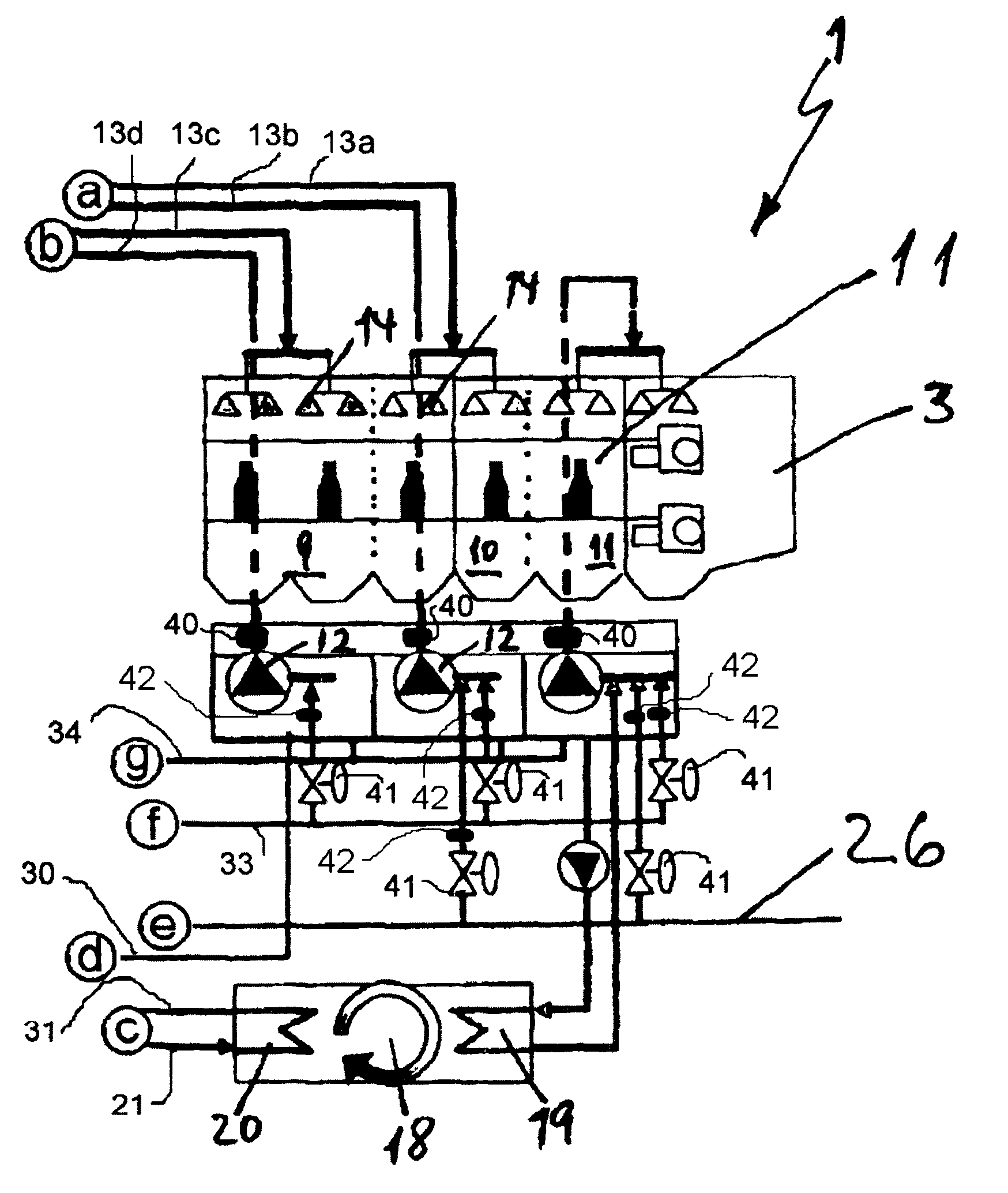
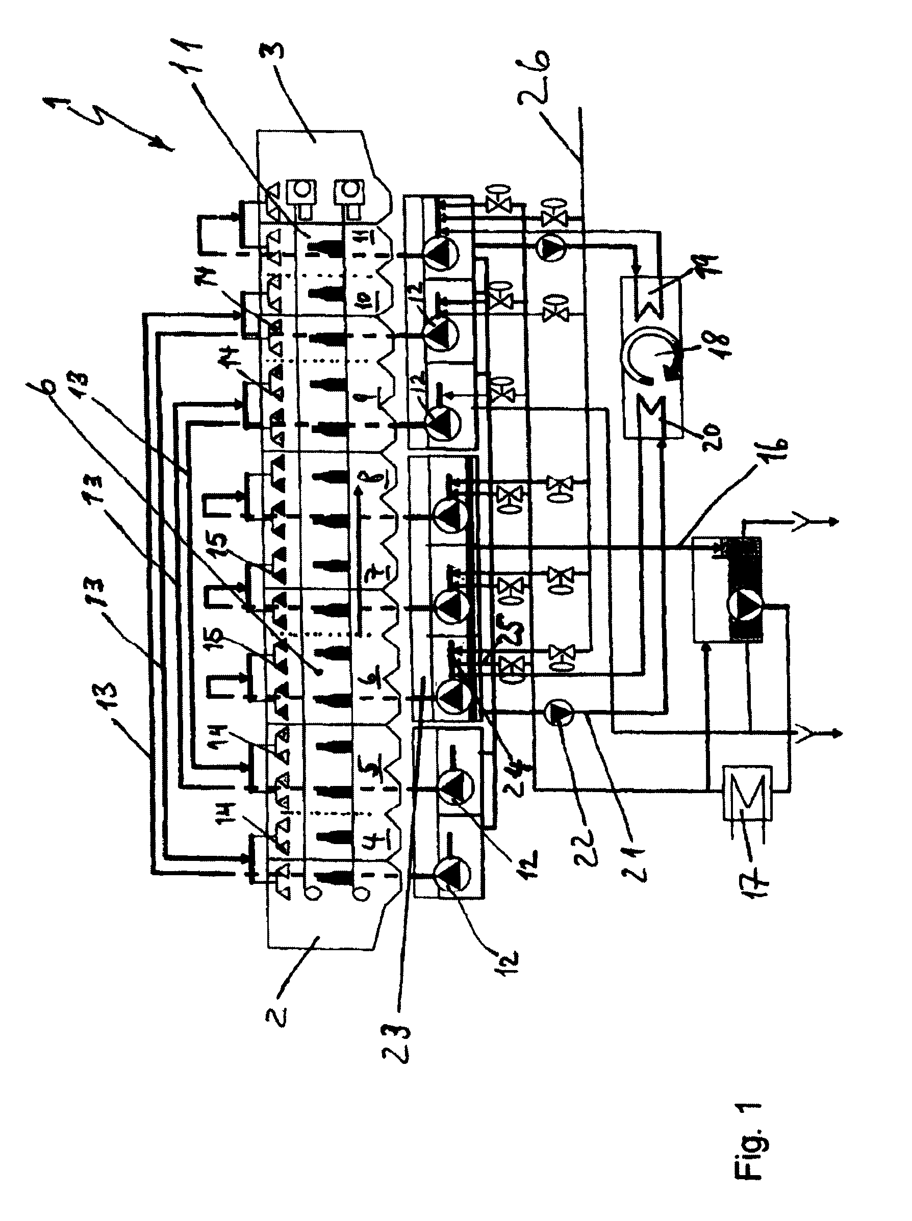
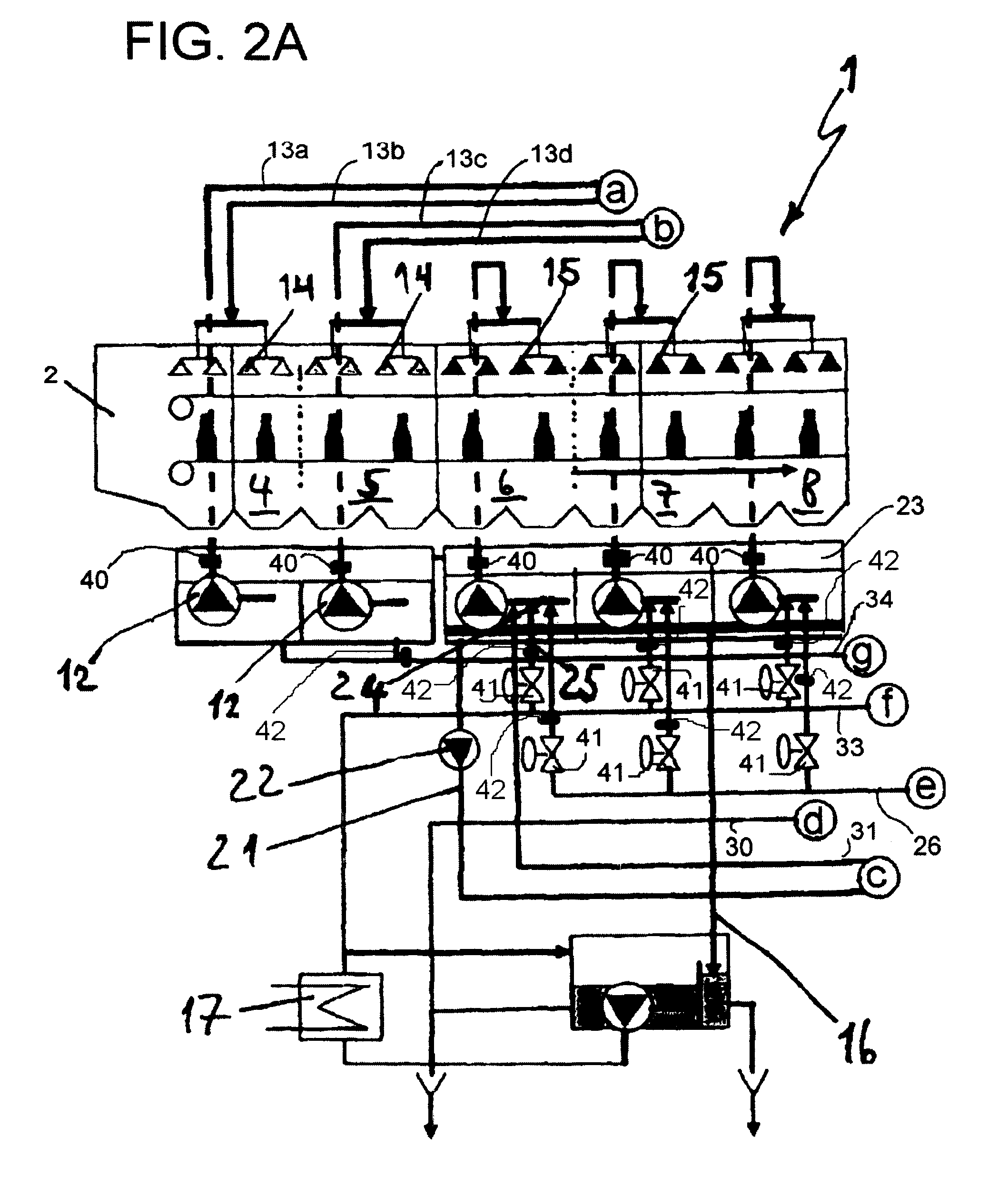
[0038]The schematic representation in FIG. 1 shows the pasteurizing device 1, which has an inlet 2, an outlet 3, and a plurality of segments 4 through 11. From left to right, consequently, schematically represented vessels that have been conducted into the inlet 2, run through heating segment 4, heating segment 5, pasteurizing segments 6, 7 and 8, cooling segment 9, cooling segment 10 and cold segment 11. The segments 4 and 10 and the segments 5 and 9 are interconnected in a recuperative manner, the collected irrigation water is collected therein, conveyed by means of pumps 12 and via the lines 13 to the respective other segment and is irrigated there by means of suitable, known irrigation devices 14. The irrigation water in the pasteurizing segments 7 and 8 is also collected and is irrigated once again as an internal circuit in the same segment by means of the irrigation devices 15. To this end, a part flow 16 is continuously removed and guided over a heat exchanger 17 for heating ...


PUM


Abstract

A beverage bottling plant for filling beverage bottles with a beverage bottle treatment machine and a beverage bottle treatment machine in a beverage bottling plant. The abstract of the disclosure is submitted herewith as required by 37 C.F.R. §1.72(b). As stated in 37 C.F.R. §1.72(b): A brief abstract of the technical disclosure in the specification must commence on a separate sheet, preferably following the claims, under the heading “Abstract of the Disclosure.” The purpose of the abstract is to enable the Patent and Trademark Office and the public generally to determine quickly from a cursory inspection the nature and gist of the technical disclosure. The abstract shall not be used for interpreting the scope of the claims. Therefore, any statements made relating to the abstract are not intended to limit the claims in any manner and should not be interpreted as limiting the claims in any manner.

Description

CONTINUING APPLICATION DATA[0001]This application is a Continuation-In-Part application of International Patent Application No. PCT / EP2007 / 011009, filed on Dec. 14, 2007, which claims priority from Federal Republic of Germany Patent Application No. 10 2007 003 976.1, filed on Jan. 26, 2007. International Patent Application No. PCT / EP2007 / 011009 was pending as of the filing date of this application. The United States was an elected state in International Patent Application No. PCT / EP2007 / 011009.BACKGROUND[0002]1. Technical Field[0003]The present application relates to a device and a method for treating containers filled with liquid, such as for example beverage bottles or beverage cans. In this case, part of the heat exchanger is realized by a heat pump being provided between one or more segments of the treating zone and those of the cooling zone.[0004]2. Background Information[0005]Background information is for informational purposes only and does not necessarily admit that subseque...

Claims


Application Information

Patent Timeline
Patent Type & Authority Applications(United States)
IPC IPC(8): A23L3/04B65B55/02
CPCA23L3/02Y02P60/85F16F1/328A23L3/04Y02A40/963
Inventor MUNZER, JAN
Owner KHS GMBH
Learn More