
Plug screw feeder for feeding cellulose pulp/chips

Active Publication Date: 2010-07-29
VALMET TECHNOLOGIES INC
View PDF7 Cites 12 Cited by
  • Summary
  • Abstract
  • Description
  • Claims
  • Application Information

AI Technical Summary

Benefits of technology

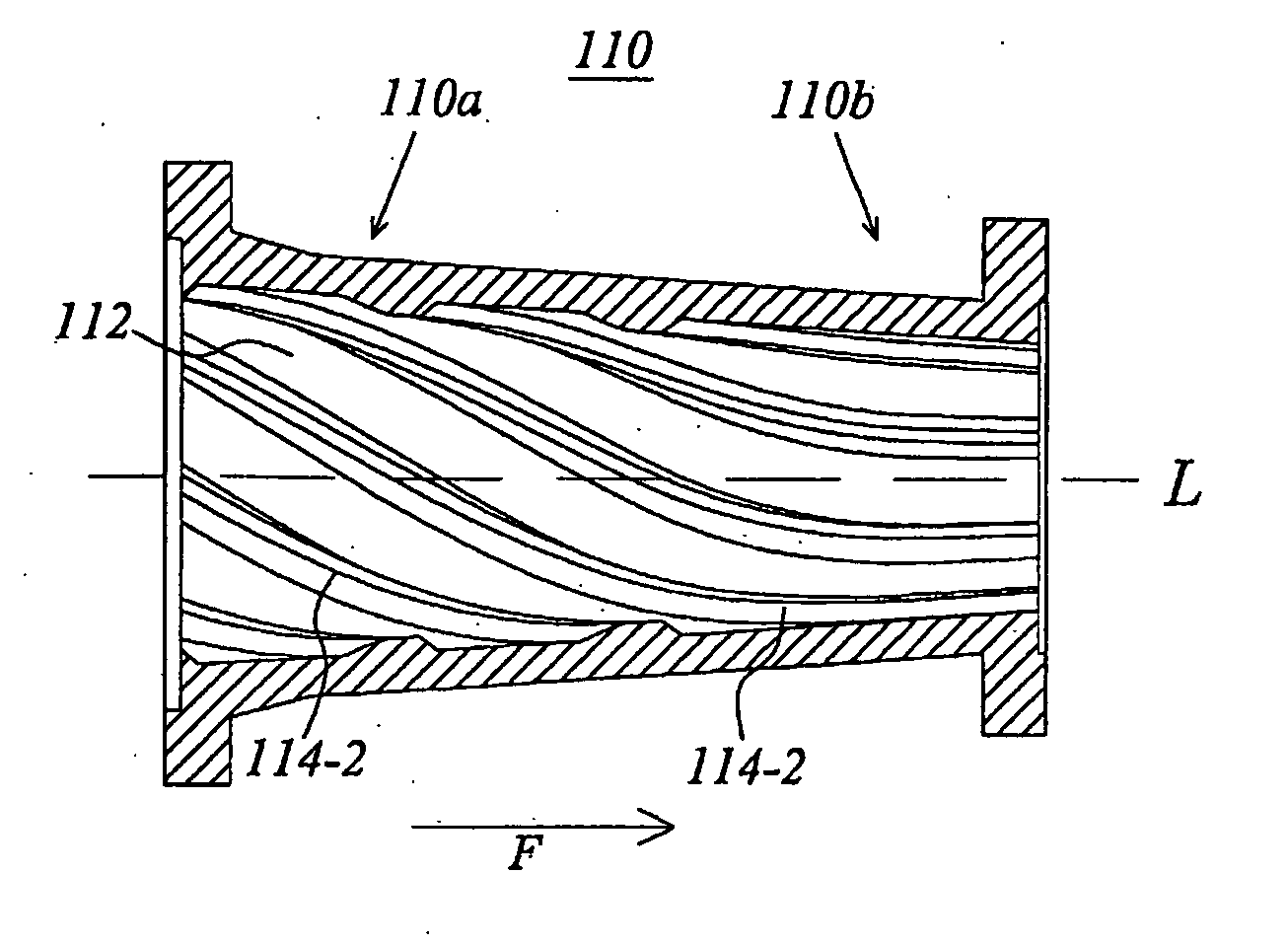
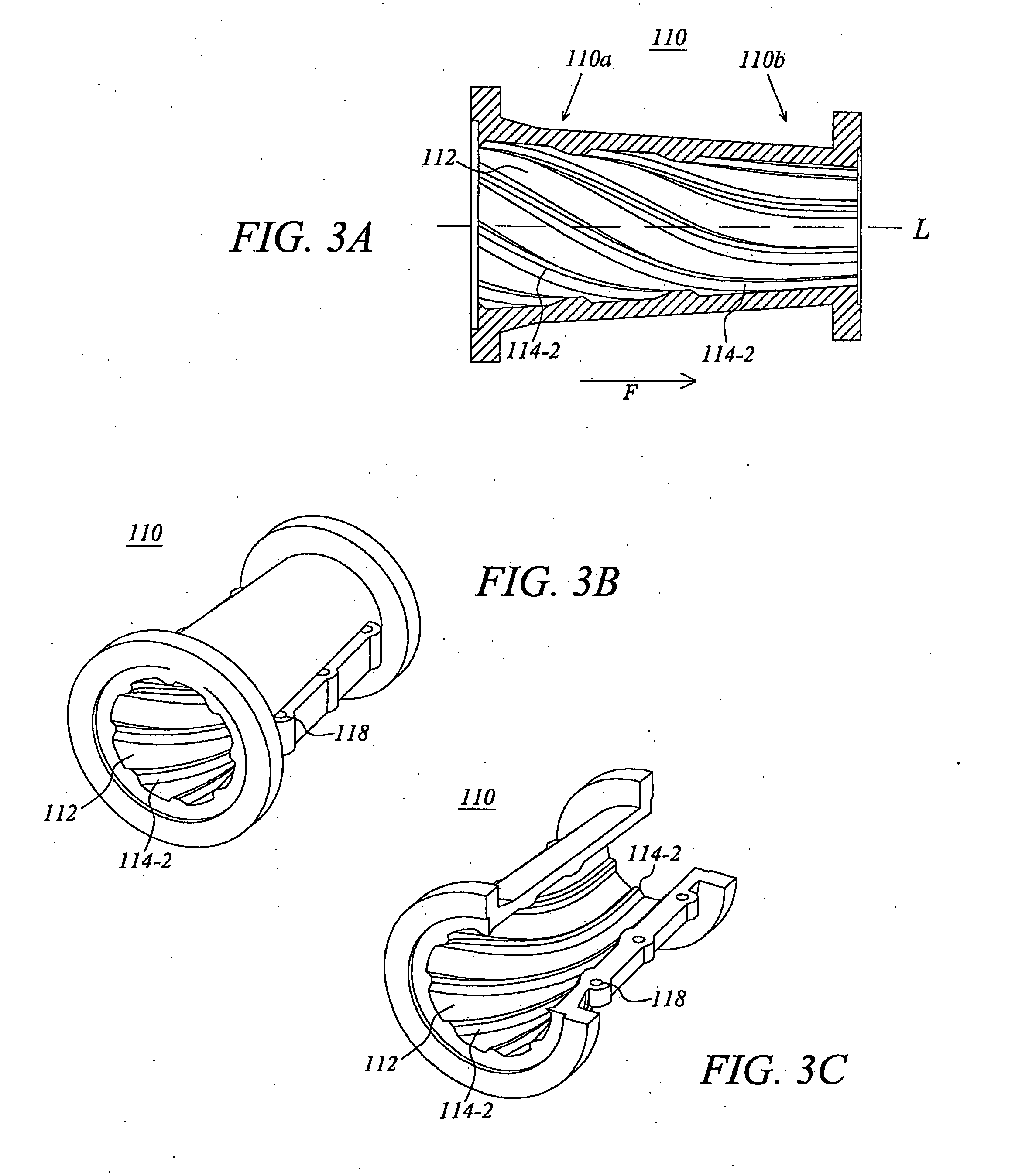
[0018]In accordance with the present invention a screw pipe unit is proposed which has bars inclined or spiral shaped at the beginning or inlet end and then in which the inclination decreases in the feed direction such that the bars are substantially straight and parallel to the longitudinal axis at a portion of the screw pipe closer to the outlet end of the screw pipe. The pulp / chip flow is efficiently fed through the improved feeding effect of the inclined bars at a first portion of the screw pipe and at a later stage in the screw pipe the dewatering properties increase. Thus, the pulp / chips can be efficiently fed and dewatered by means of one and the same plug screw feeder.
[0019]Preferred embodiments of the present invention relate to a screw pipe unit with a gradual decrease in the bar inclination (stepwise or continuously), thus avoiding the risk that comparatively abrupt change(s) in the degree of inclination will affect the shape and other properties of the plug in a negative manner.
[0020]A screw pipe in accordance with the present invention with straight or almost straight bars near the pipe output end is suitable for being connected e.g. to a slotted plug pipe with straight bars, whereby the plug formation and dewatering is further improved.

Problems solved by technology

However, such spiral screw pipes result in less efficient dewatering.
Furthermore, spiral screw pipes could be inappropriate for use together with known types of slotted plug pipes with straight bars.

Method used


Image

  • Plug screw feeder for feeding cellulose pulp/chips
  • Plug screw feeder for feeding cellulose pulp/chips
  • Plug screw feeder for feeding cellulose pulp/chips

Examples


Embodiment Construction

[0035]The following detailed description refers to the drawings, in which similar or corresponding elements will be denoted by the same reference numbers.

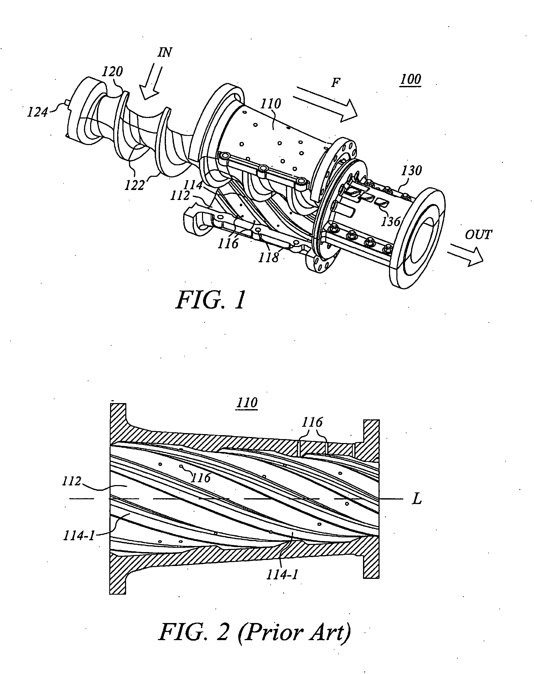
[0036]Referring first to FIG. 1, this figure shows key components of a plug screw feeder in which the present invention can be used. The plug screw feeder 100 (sometimes also referred to as screw conveyor, transport screw, etc.) comprises a screw pipe 110, a screw 120 (also referred to e.g. as feed screw or plug screw), and a plug pipe 130. Cellulose pulp or chips, depending on the application in which the plug screw feeder 100 is used, in the illustrated example as input to the horizontal plug screw feeder from above, to reach an input end of the screw pipe. This is schematically indicated by the block arrow IN. The screw 120 is rotated about shaft 124 arranged along the longitudinal axis of the plug screw feeder 100, whereby cooperation between the screw 120 and enclosing screw pipe 110 causes a feeding effect and generally also ...


PUM

PropertyMeasurementUnit
Angleaaaaaaaaaa
Angleaaaaaaaaaa
Angleaaaaaaaaaa

Abstract

A screw pipe unit intended to cooperate with and at least partly enclose a screw in a plug screw feeder for cellulose chips / pulp is provided. The screw pipe unit comprises a plurality of openings for filtrate dewatered from the chips / pulp in the screw pipe when the plug screw feeder is in operation. The screw pipe is, on at least a portion of its inner surface, provided with bars inclined with respect to the longitudinal axis of the screw pipe. The angle of inclination of the bars decreases in the longitudinal direction, from a first portion of the screw pipe unit with maximum inclination to a second portion of the screw pipe unit with bars substantially parallel to the axis, the second portion being further away from the inlet end of the screw pipe unit than the first portion.

Description

CROSS-REFERENCE TO RELATED APPLICATIONS[0001]The present application is a national phase entry under 35 U.S.C. §371 of International Application No. PCT / SE2008 / 050428 filed Apr. 16, 2008, published in English, which claims priority from Swedish Application No. 0701594-4 filed Jun. 29, 2007, all of which are incorporated herein by reference.FIELD OF THE INVENTION[0002]The present invention relates to a plug screw feeder for feeding cellulose pulp / chips.BACKGROUND OF THE INVENTION[0003]In the pulp and paper industry, plug screw feeders are well known devices used in different applications for transporting cellulose pulp / chips in such way that a plug is formed, sealing against a higher (or lower) pressure at the output end of the feeder. The plug transport is achieved by means of a screw interacting with some kind of pipe member, often referred to as screw pipe. The screw pipe may, for example, present a tapering shape.[0004]It is often desirable to dewater the material transported in ...

Claims


Application Information

Patent Timeline
IPC IPC(8): B30B9/12D21C7/06
CPCB30B9/122B65G33/14D21B1/22D21C7/06D21B1/02
Inventor SVEDBERG, PETER
Owner VALMET TECHNOLOGIES INC
Learn More