
Inflatable Solar Collector

Inactive Publication Date: 2010-07-29
HELIOVIS
View PDF8 Cites 35 Cited by
  • Summary
  • Abstract
  • Description
  • Claims
  • Application Information

AI Technical Summary

Benefits of technology

[0004]It is an object of the invention to eliminate the above-mentioned disadvantages, i.e. to simplify the manufacture and the tracking, and to increase the area yield for energy production.
[0007]One preferred embodiment of the inflatable solar collector according to the invention is characterized in that wires or the like are stretched at defined intervals on the side of each reflector membrane opposite its reflective side. The wires extend transverse to the longitudinal extension of the tube, and each absorber is effectively situated at the center between two wires. As a result of this design, due to the fact that a lower pressure is generated on the side of the reflector membrane opposite the reflective side than on the top side when the solar collector is acted on by pressure, the membrane is not cylindrically curved. Since the membrane is supported by the wires, it assumes the shape of spherical dome shell surfaces arranged in a row. Accordingly, one absorber is provided above the center of each individual section, thus achieving intensive bundling of the incoming solar energy.
[0013]For terrestrial use of the inflatable solar collector according to the invention, to allow ground anchoring on the one hand, and simple tracking of the sun's position on the other hand, it has proven advantageous to fasten preferably mutually intersecting anchoring bands at essentially diametrically opposed outer sides of the tube. When such oppositely situated, and preferably also mutually intersecting, bands are anchored to the ground at their free ends, mounting is ensured, and the solar collector can be rotated corresponding to the solar trajectory.
[0016]When using the inflatable solar collector according to the invention in the air, it is advantageous for the tube to be filled with a buoyancy gas. In this case the solar collector may be floated above the ground without additional auxiliary means. To allow a solar collector filled in such a manner with buoyancy gas to track the solar position in each case, it has proven advantageous to embed in the tube at least one conductor loop which is connected to an electrical power source. By use of such a conductor loop, i.e. multiple windings together with a coil, a magnetic field may be generated which allows positioning of the solar collector by interaction with the earth's magnetic field.

Problems solved by technology

However, the spherical shape is disadvantageous for these solar collectors, since manufacturing it is complex, and complicated biaxial tracking is necessary.
Use as spherical heliostats represents a further disadvantage, since due to the shading problem caused by solar tower power plants it is not possible to position such solar collectors relatively closely together.
Therefore, the area yield for energy production is not optimal.

Method used


Image

  • Inflatable Solar Collector
  • Inflatable Solar Collector

Examples


Embodiment Construction

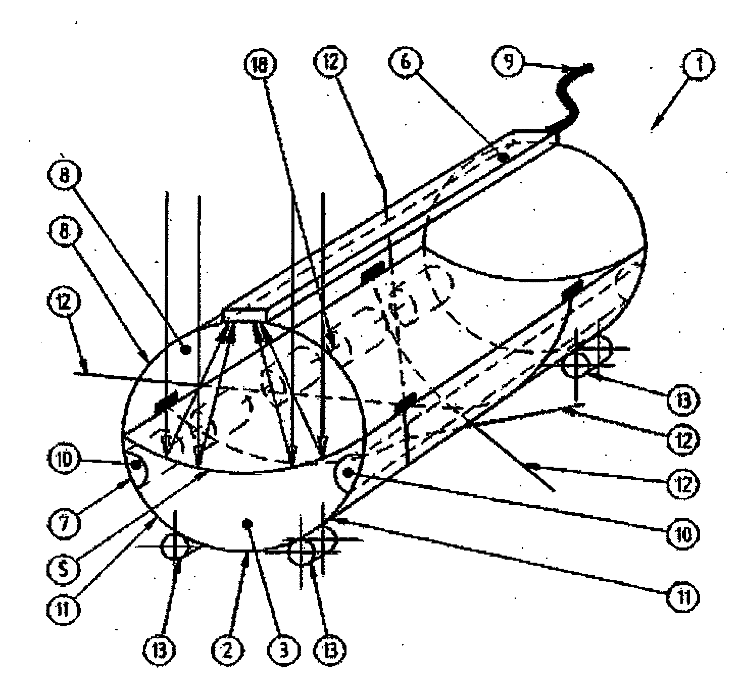
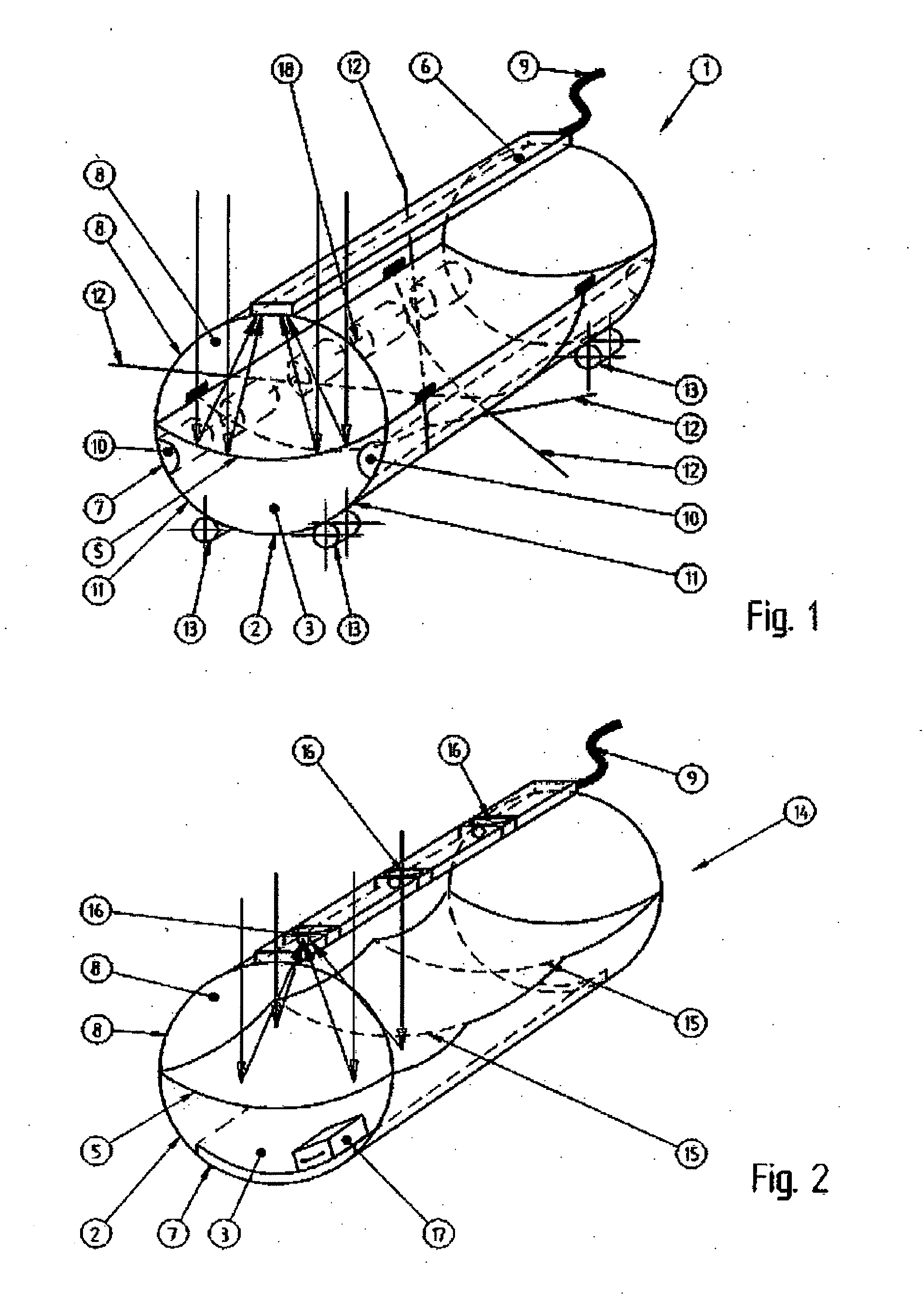
[0020]Referring to FIG. 1, the inflatable solar collector 1 has a cylindrical tube 2 as a sleeve. The tube is transparent, at least above a reflector membrane 5 which divides the tube 2 into two chambers 3, 4. In the illustrated example, the reflector membrane 5 is reflective on the top, upwardly facing side and extends essentially diametrically across the tube over the entire length of tube 2. An elongated absorber 6 is situated above the reflector membrane 5, approximately in the region of the lateral surface of the tube 2. This may be, for example, a pipe through which media flow. The chambers 3, 4 and the absorber 6 are connected to corresponding connecting lines 7, 8, 9. Two ballast chambers 10 are situated below the reflector membrane, and may be filled or emptied through lines 11 as needed. As shown in FIG. 1, the ballast chambers may be further divided into subchambers 18 which are connected via lines. Anchoring bands 12 are fastened at diametrically opposed outer sides of t...


PUM


Abstract

The invention relates to an inflatable solar collector (1) comprising an at least partially transparent sleeve divided at least into two chambers (3, 4) which are separated by a reflector membrane (5) reflecting on one side and which can respectively receive a gas, and at least one absorber (6) arranged opposite the reflective side of each reflector membrane (5). The sleeve is a cylindrical tube (2) and each reflector membrane (5) extends along the length thereof. The absorber(s) (6) is / are arranged along at least one focus line extending along the length thereof. Fillable ballast chambers (10) can be provided beneath the reflector membrane (5). Anchoring strips (12) are used for anchoring and bearing rolls (13) for support.

Description

RELATED APPLICATIONS[0001]This application claims the priorities of Austrian Patent Applications Nos. AT 505,075 B1 and AT 504,916 B1 and of PCT Application No. PCT / AT2008 / 000177, the disclosures of which are incorporated herein by reference.BACKGROUND OF THE INVENTION[0002]The invention relates to an inflatable solar collector with an at least partially transparent sleeve divided into at least two chambers which are separated by a reflector membrane that is reflective on one side, and which can be independently acted on by a gas, and has at least one absorber that is oppositely situated from the reflective side of each reflector membrane.[0003]Such a spherical inflatable solar collector, which may be used for terrestrial energy production, has become known from a research report. All solar collectors of this type are based on the principle that solar radiation is bundled by the reflector membrane and directed to the absorber, which converts the solar radiation into energy. As the r...

Claims


Application Information

Patent Timeline
IPC IPC(8): F24J2/36F24S10/40F24S23/71F24S23/74
CPCY02E10/42Y02E10/44Y02E10/47F24S23/715F24S23/745F24S10/45F24S20/80Y02E10/40
Inventor HOEFLER, JOHANNES
Owner HELIOVIS
Learn More