Eureka AIR delivers breakthrough ideas for toughest innovation challenges, trusted by R&D personnel around the world.

Process for the production of a component, and fibre-reinforced thermoplastic component

Inactive Publication Date: 2010-07-29
AIRBUS OPERATIONS GMBH
View PDF8 Cites 10 Cited by
  • Summary
  • Abstract
  • Description
  • Claims
  • Application Information

AI Technical Summary

Benefits of technology

[0013]It is decisive for the method according to the invention that the interlaminar sliding of the fibre layers that necessarily take place is already largely terminated and that only the final geometric shaping and consolidation takes place during the second forming step by the application of pressure in the pressing tools, which should ideally be on all sides and acting with the same force. To produce complex component geometries one plane is no longer successively formed in the inventive method from a previously bent plan by renewed bending after renewed plasticisation, but all the component planes required for the design are applied almost “latently” when producing the preform in the first method step. According to the method according to the invention the sliding of the fibre layers always takes place essentially perpendicularly to the edge line concerned, so that no strength-reducing impairments (e.g. distortions, displacements) in the fibre reinforcement result from the forming operations.
[0017]Because the component has at least two edge lines running at an angle of approx. 0° to 90° to each other, and the edge lines lie in at least two different planes, the component meets a multiplicity of design requirements in the case of a simultaneously force-flow-orientated course of the reinforcing fibres, and can therefore be used in large quantities, for example, for connecting the CFP annular ribs to a CFP outer fuselage skin of an aircraft The component also has very low weight with a simultaneous high static and dynamic loading capacity, and can also be produced economically in large quantities with close component tolerances.

Problems solved by technology

The component design is greatly restricted by this condition.
This may result in impairment of the process and integrity of the fibre reinforcement during forming.

Method used


Image

  • Process for the production of a component, and fibre-reinforced thermoplastic component
  • Process for the production of a component, and fibre-reinforced thermoplastic component
  • Process for the production of a component, and fibre-reinforced thermoplastic component

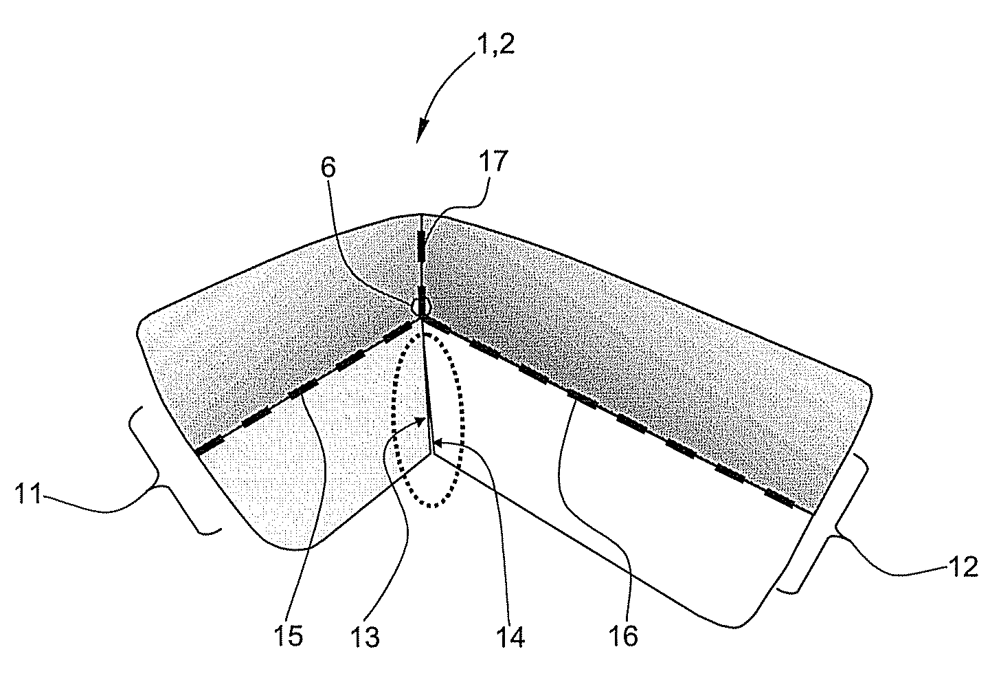
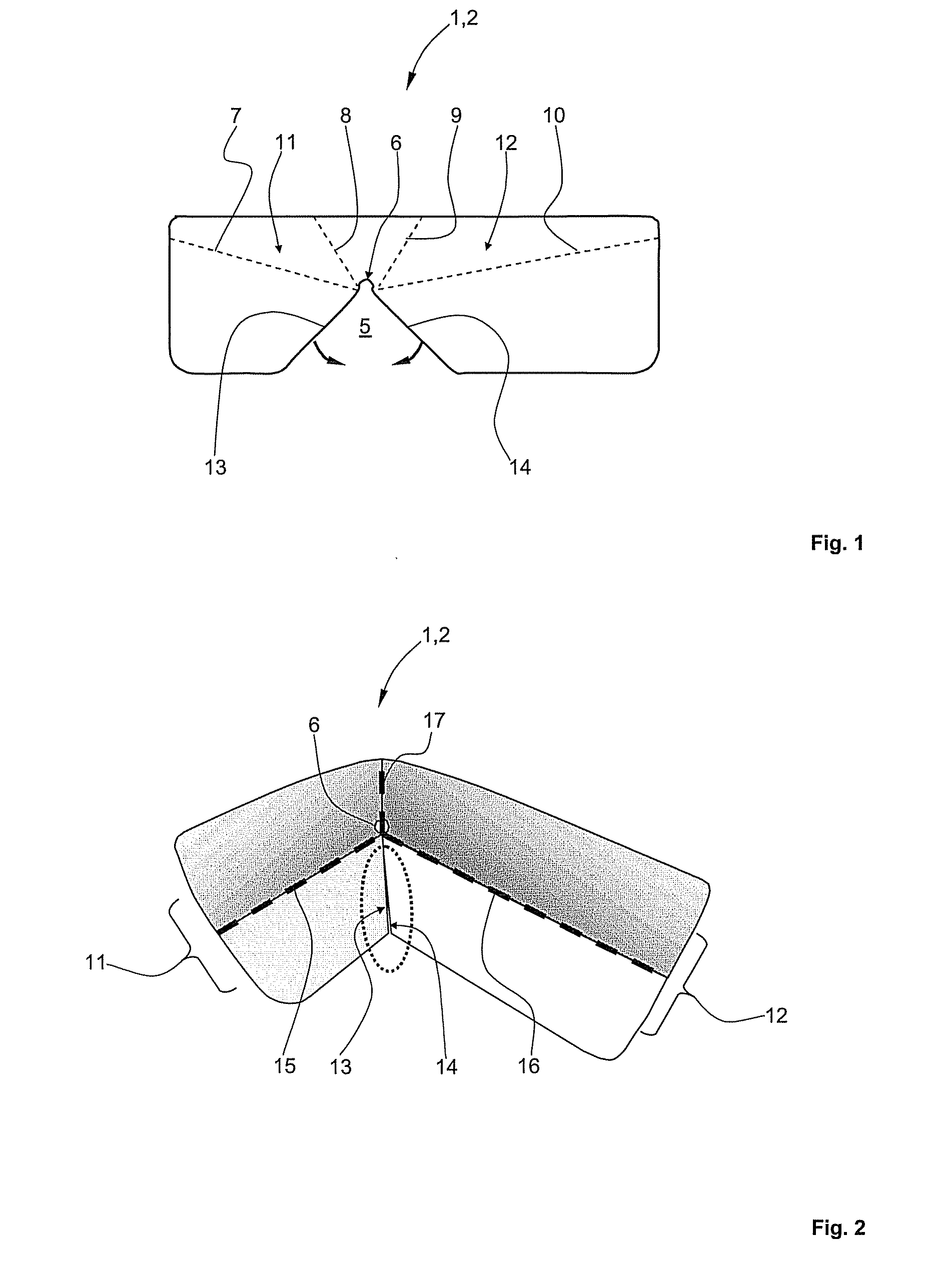
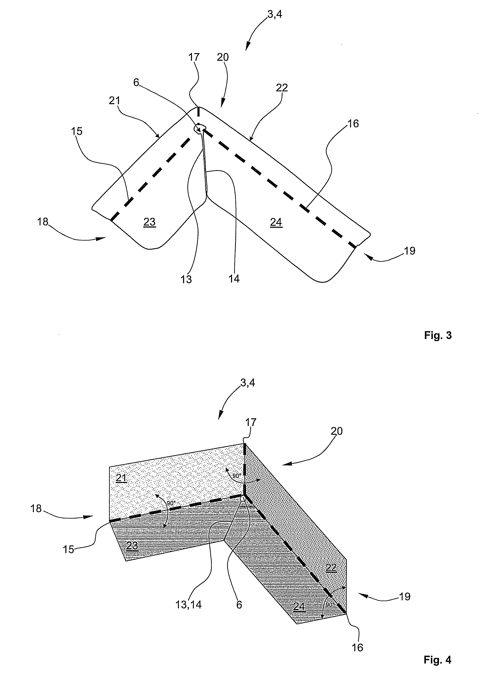
Examples


Embodiment Construction

[0026]In the drawing the same structural elements each have the same reference number. From now on in the description reference is initially made to FIGS. 1 to 4 simultaneously.

[0027]FIG. 1 shows an elevation of a blank 1, which is initially still flat and which serves as a preliminary stage for producing preform 2 and finished component 3 by means of several bending operations. Finished component 3 is a (connecting) angle 4 or a gusset plate for the interior fastening of annular ribs to a fuselage cell skin of an aircraft in the exemplary embodiment shown. Blank 1 is preferably formed with a thermoplastic material reinforced with several fibre layers, particularly carbon fibre layers. PPS, PEEC, PECC in particular, or any combination thereof, are considered as suitable thermoplastic material.

[0028]The single-piece blank 1 has an essentially V-shaped cut-out 5 whose tip is able to run into an approximately circular recess 6 for stress relief of section 5. Edge lines 7 to 10, shown a...


PUM

PropertyMeasurementUnit
Angleaaaaaaaaaa
Angleaaaaaaaaaa
Pressureaaaaaaaaaa

Abstract

The invention relates to a method for producing a component for connecting a fuselage cell skin to an annular rib of an aircraft, wherein the component is formed by bending of a flat blank along at last two edge lines and wherein the blank is formed by a CFRP.According to the invention the interlaminar sliding of the fibre layers is largely completed in a first forming step, whilst in a second forming step a consolidation of the component takes place by the use of pressure from the press on all sides by means of an upper tool and a lower tool. This enables complex components with at least two edge lines to be produced, which edge lines run at angles of approximately, preferably at angles of 309° to 90°, to each other, and which edge lines also lie in at least two different planes.

Description

CROSS-REFERENCE TO RELATED APPLICATIONS[0001]This application is a continuation of PCT International Application No. PCT / EP2008 / 058481 filed Jul. 2, 2008, which claims the benefit of U.S. Provisional Application No. 60 / 964,170, filed Aug. 9, 2007 and German Patent Application No. 10 2007 037 649.0, filed Aug. 9, 2007, the entire disclosures of which are herein incorporated by reference.FIELD OF THE INVENTION[0002]The invention relates to a method for producing a component, in particular an angle, for connecting a fuselage cell skin to an annular rib of an aircraft, where the component is to be formed by bending a flat blank several times along at least two edge lines, and where the blank is formed with a thermoplastic plastic reinforced with several layers of fibres.[0003]The invention also relates to a component of a thermoplastic plastic reinforced with a multiplicity of fibre layers, the component formed by bending, particularly according to the method of the invention.[0004]The ...

Claims


Application Information

Patent Timeline
IPC IPC(8): B29C53/06
CPCB29C53/04B29C70/222B29C70/345B29C2793/0081B29K2071/00B29K2081/04Y10T156/1036B29K2277/10B29K2707/04B29K2709/08B29L2009/00B29L2031/3076Y02T50/433B29K2101/12Y02T50/40
Inventor EDELMANN, KLAUSFRESE, TANJASTOEVEN, TIMOWIRTZ, TOBIAS
Owner AIRBUS OPERATIONS GMBH
Why Eureka
Eureka Blog
Learn More