Device for measuring a distance and method for measuring said distance

a technology for measuring devices and distances, applied in distance measurement, optical radiation measurement, instruments, etc., can solve the problems of excessive cost of this solution, excessive loss of useful information, and difficulty in implementation of the architecture just described above, and achieve high static and dynamic fill factor, reduce size, and high precision

Active Publication Date: 2021-08-03
SICK AG
View PDF6 Cites 0 Cited by
  • Summary
  • Abstract
  • Description
  • Claims
  • Application Information

AI Technical Summary

Benefits of technology

[0032]It is another object of the present invention to provide a measuring device which is capable of maintaining high precision in the determination of said distance, also in the presence of a sudden change of the external measuring conditions.
[0033]It is a further object of the present invention to provide a measuring device with a high static and dynamic fill factor.
[0034]It is another object of the present invention to provide a measuring device characterized by reduced size and simplified architecture.
[0035]It is a further object of the present invention to provide a measuring device involving moderate energy consumption.

Problems solved by technology

This solution, however, poses some recognized drawbacks, first of all the fact that in practical application the architecture just described above is difficult to implement, as the definition of a number of processing elements at least equal to the number of sensitive units would determine an excessive size of the receiving means and, consequently, of the entire device.
Furthermore, also the cost of this solution would be excessive.
Therefore, said architecture is disadvantageously affected by the fact that the photons of the light radiation reflected by the reference object and impacting the receiving means at the level of the processing elements, which are present in a large number, cannot be detected, thus causing an excessive loss of useful information.
Finally, the large number of processing elements required determines, to disadvantage, high energy consumption for the operation of the receiving means and, consequently, of the entire measuring device.
However, said second embodiment poses an important drawback, which is represented by less efficiency in the determination of said distance compared to the first architecture.
Therefore, to disadvantage, said architecture statistically determines a reduction of the signal-to-noise ratio compared to the first type of measuring device described above, due to the reasons which have just been explained.
However, a loss of useful information may occur also in this case, when a photon impacts the sensitive surface of a sensitive unit in a time interval during which the processing element is busy managing a different processing unit.
Furthermore, said third embodiment poses a further recognized drawback which lies in that it takes more time to carry out the measuring operations compared to the previous measuring devices of the known art, due to the selection sequence performed by the multiplexer.
However, to disadvantage, said embodiment loses its effectiveness at the moment when, during the various measuring operations, the external operating conditions change with respect to the conditions observed during said setting step.
In addition to the disadvantages of the specific architectures just described above in relation to the measuring devices made according to the known art, it is possible to mention a further drawback shared by all of them.
This drawback, in particular, occurs in the case where there is a high luminous flux impacting the sensitive area of the receiving means, independently of whether it is due to the light radiation emitted by the emission means or to the background noise, for example sunlight.
This means, to disadvantage, that the risk of loss of useful information, meaning the risk of failure to detect the impact of photons belonging to the light radiation emitted by the emission means, can reach unacceptable values.
Again, the presence of said “pile-up” phenomenon in the case of a high luminous flux determines, to disadvantage, a drastic reduction of the actual fill factor value following said sudden saturation of the sensitive units.

Method used


Image

  • Device for measuring a distance and method for measuring said distance
  • Device for measuring a distance and method for measuring said distance
  • Device for measuring a distance and method for measuring said distance

Examples


Embodiment Construction

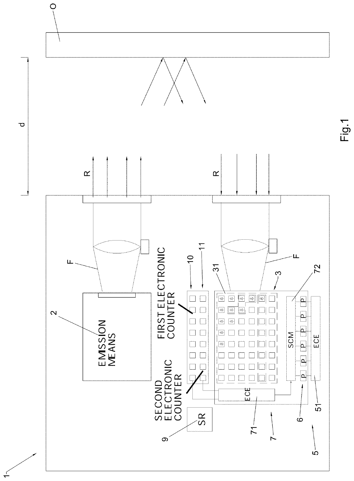
[0045]The measuring device that is the subject of the invention and is suited to measure the distance d of a reference object O, or of a plurality of reference objects O, is represented in FIG. 1, where it is indicated as a whole by 1.

[0046]As explained below, the measuring device 1 is configured to carry out in succession a plurality of measuring operations Ai for the purpose of determining the value of said distance d with great precision.

[0047]As shown in FIG. 1, the measuring device 1 of the invention comprises emission means 2 suited to emit light radiation R directed towards the reference object O during a predetermined time interval I for each one of said measuring operations Ai in sequence.

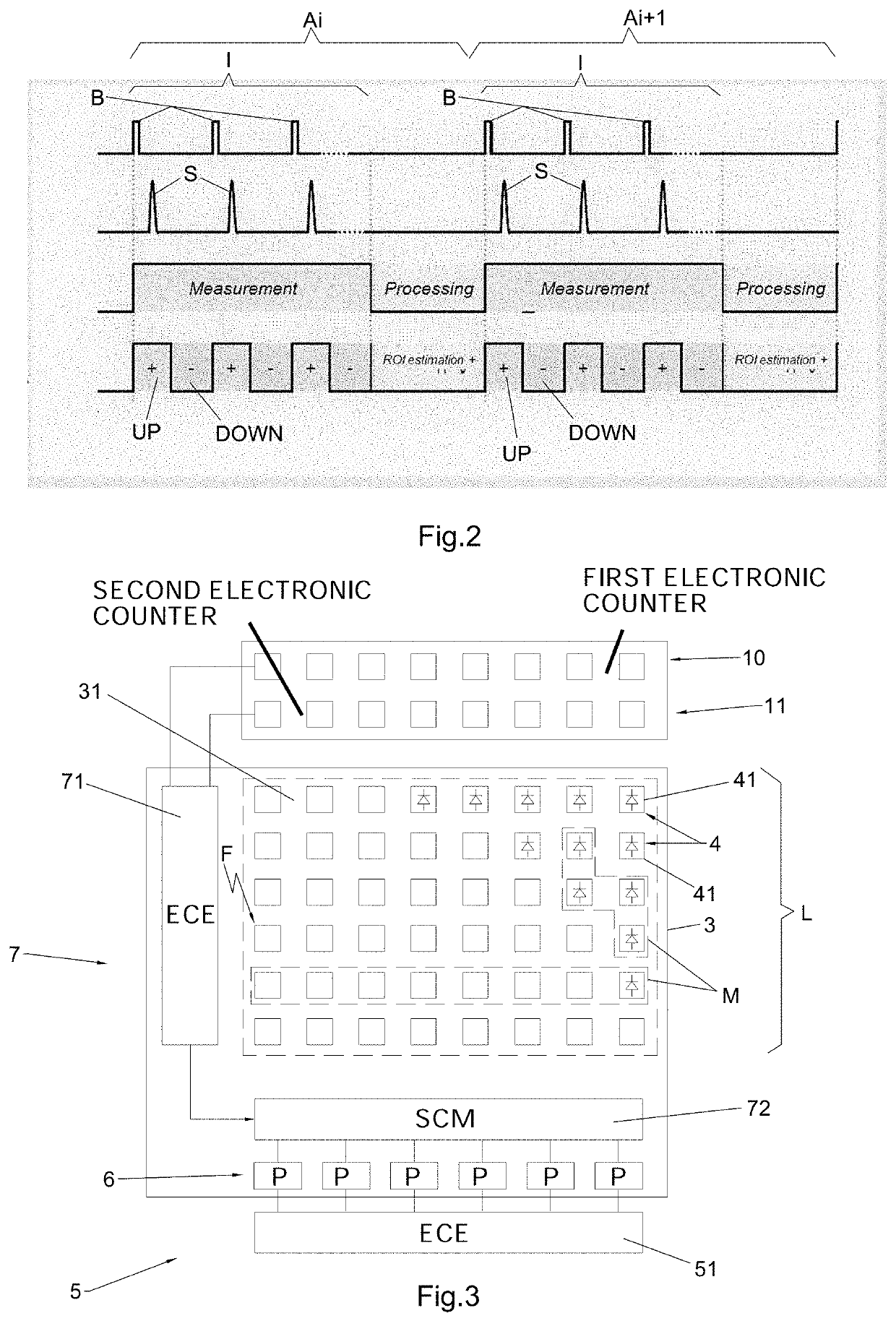
[0048]Said plurality of measuring operations Ai in sequence is illustrated in the time chart shown in FIG. 2.

[0049]According to the preferred embodiment of the invention, said emission means 2 are configured to emit, at each time interval I related to each one of the measuring operations A...


PUM


Abstract

Measuring device (1) suited to measure the distance (d) of a reference object (O), configured so that it performs a plurality of measuring operations (Ai) in succession and comprising emission means (2) suited to emit a light radiation (R), receiving means (3) comprising a sensitive area (31) which is sensitive to the light radiation (R) and which is provided with a number M of sensitive units (4), each one of the sensitive units (4) being configured to generate an electrical signal (S), a first processing unit (5) comprising Ne processing elements (6), each one of said Ne processing elements (6) being configured to receive the electrical signal (S) for determining the time of impact (t) of a photon (F) on the sensitive units (4) and for calculating the value of said distance (d). The measuring device (1) comprises a second processing unit (7) configured to receive the electrical signals (S), processing the electrical signals (S) in such a way as to select a number Nu of sensitive units (4) impacted by the photons (F), associating each one of the Nu sensitive units (4) to one of the Ne processing elements (6), in such a way that, at the moment of the successive measuring operation (Ai+1), the distance (d) is determined by each one of the Nu sensitive units (4) selected.

Description

BACKGROUND1. FIELD[0001]The invention concerns an improved device suited to measure the distance between the device itself and a reference object through the use of light radiation. The invention, furthermore, concerns a method for measuring said distance by means of said measuring device.2. DESCRIPTION OF THE RELATED ART[0002]Devices for measuring distances are known, which are based on the emission of light radiation directed towards a reference object and on the detection of said light radiation reflected by the reference object itself.[0003]In detail, said measuring devices comprise means suited to emit said light radiation and receiving means comprising an area which is sensitive to said light radiation. The measuring devices belonging to the known art furthermore comprise a processing unit capable of determining the time interval that elapses between the emission of said light radiation by the emission means and the moment when said light radiation is detected by the receiving...

Claims


Application Information

Patent Timeline
Patent Type & Authority Patents(United States)
IPC IPC(8): G01C3/08G01S7/4865G01S7/481G01C15/00G01S7/497G01S7/4863G01J1/18G01J1/44G01S7/48G01S7/4861G01S17/10
CPCG01S7/4865G01C3/08G01C15/002G01J1/18G01J1/44G01S7/4808G01S7/4816G01S7/4861G01S7/4863G01S7/497G01S17/10G01J2001/442G01J2001/4466G01S17/08
Inventor PERENZONI, DANIELESTOPPA, DAVIDGASPARINI, LEONARDOPERENZONI, MATTEOMASSARI, NICOLAZWÖLFER, ULRICHWASLOWSKI, KAIBOHLI, ALEXANDERALBERT, MICHAELWIETHEGE, FRIEDHELM
Owner SICK AG
Why Eureka
Try Eureka