Caliper brake

a brake and caliper technology, applied in the field of caliper brakes, can solve the problems of uneven wear of the statator, slow response time, and more frequent replacement, and achieve the effects of reducing the number of components, reducing the weight and cost of the brake, and improving the response time of the brak

Inactive Publication Date: 2010-07-29
LAMBERT BRAKE
View PDF22 Cites 4 Cited by
  • Summary
  • Abstract
  • Description
  • Claims
  • Application Information

AI Technical Summary

Benefits of technology

[0007]It is an object of another aspect of the present invention to provide a caliper brake, as above, wherein the actuating lever pivots about a pin on the cable bracket to reduce the number of components and improve the response time of the br

Problems solved by technology

A common problem with conventional mechanically actuated caliper brakes relates to the positioning of the cable relative to the actuating lever.
This moment causes the stators to wear unevenly, thereby requiring more frequent replacement.
Another frequent problem encountered in conventional caliper brakes is a slow response t

Method used


Image

  • Caliper brake
  • Caliper brake
  • Caliper brake

Examples


Embodiment Construction

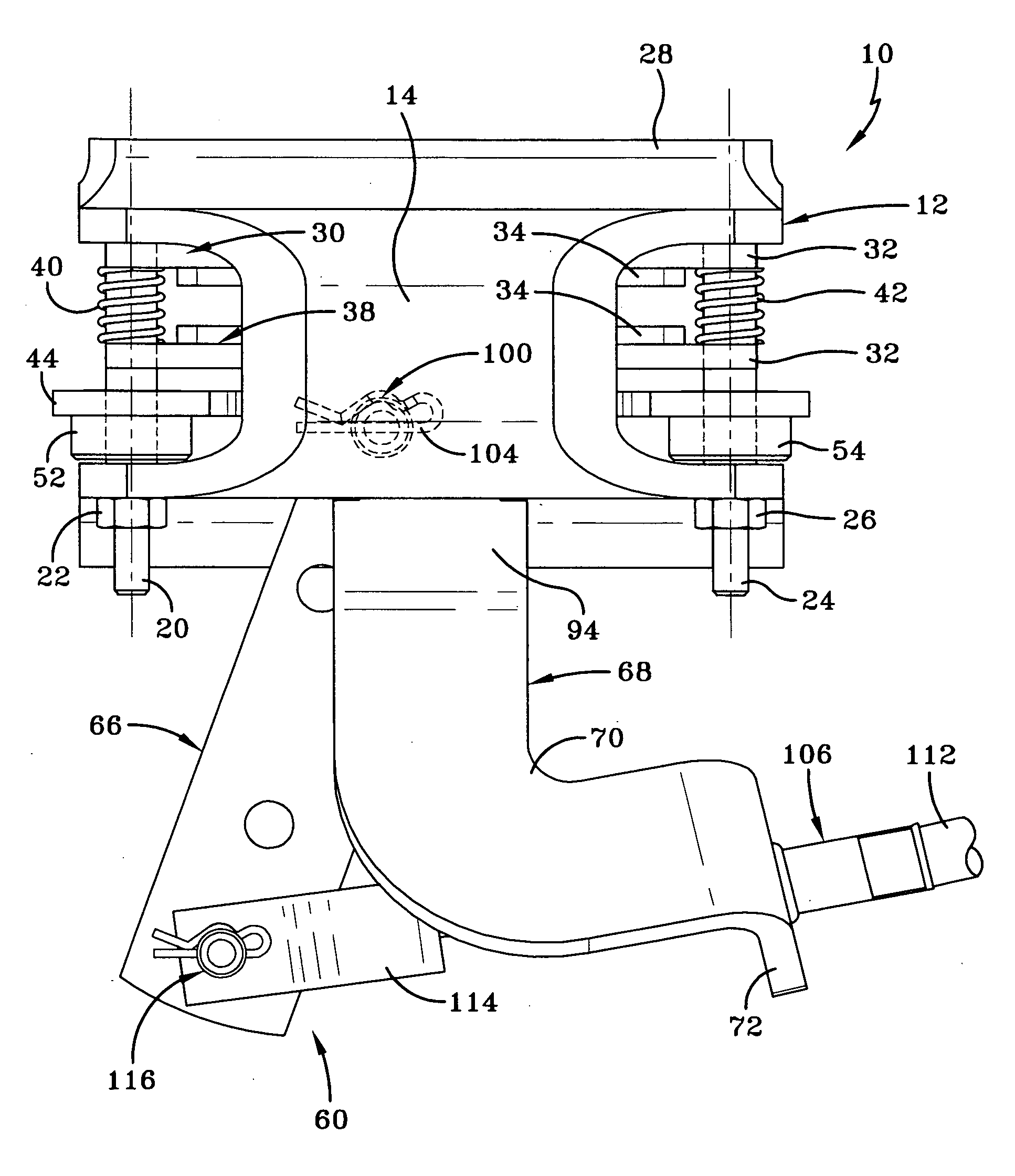
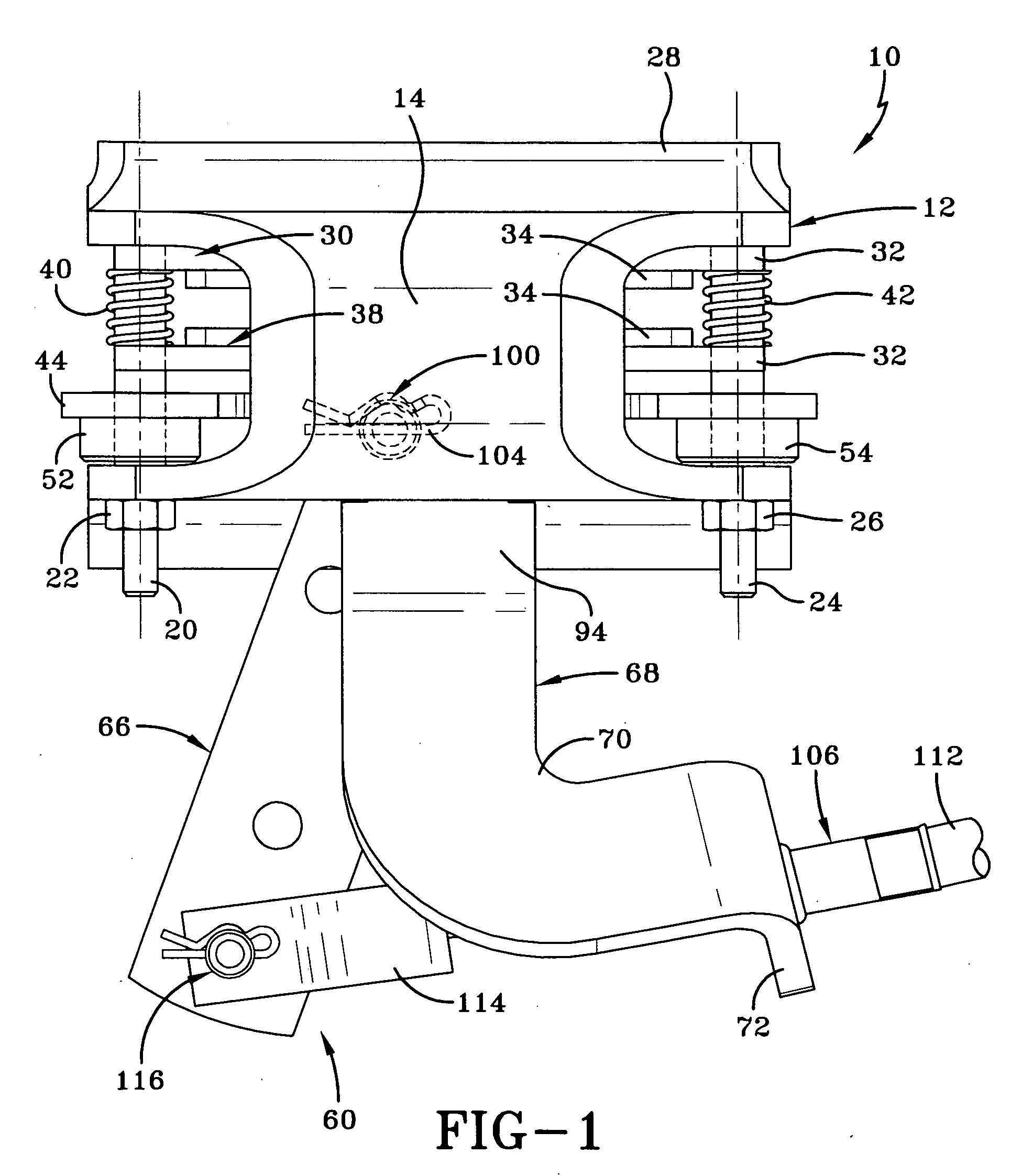
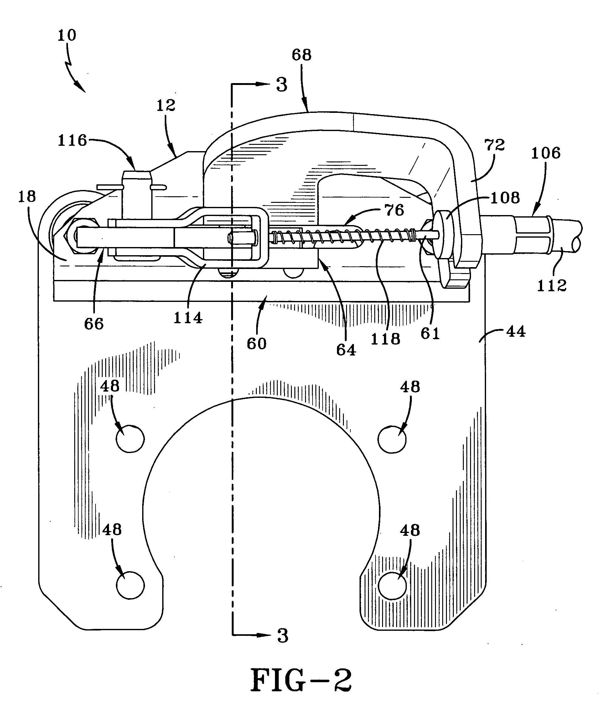
[0022]A caliper brake made in accordance with the present invention is indicated generally by the numeral 10. Caliper brake 10 includes a housing, generally indicated by the numeral 12, having a top wall 14, and opposed sidewalls 16 and 18 (FIG. 3). Housing 12 has a generally U-shaped cross-section, with sidewall 16 and sidewall 18 being displaced from one another and connected by top wall 14. A bolt 20 is received in a pair of coaxial holes in sidewall 16 and sidewall 18, and is secured therein by a nut 22 positioned adjacent to sidewall 18. Another bolt 24 is received in a separate pair of coaxial holes in sidewall 16 and sidewall 18 displaced from the bolt 20, and is secured therein by a nut 26 positioned adjacent to sidewall 18. A secondary plate 28 may be provided adjacent to sidewall 16 secured by bolt 20 and bolt 24 passing through apertures therein. Secondary plate 28 adds rigidity to sidewall 16.

[0023]A first stator assembly 30 is provided within housing 12 and is slidably ...


PUM


Abstract

A caliper brake including a housing, an opening in the housing, and an actuating assembly received in the opening. The actuating assembly includes an actuating lever having a cam surface and a pivot aperture, a cable bracket having a cable retaining flange, a pivot aperture, and a retaining portion, and a pin received through said pivot apertures to rotatably secure the actuating lever to the cable bracket. The retaining portion of the cable bracket acts to secure the actuating assembly in the opening of the housing without the need for mechanical fasteners. A pivot plate may also be provided, the pivot plate having a pivot aperture and a retaining portion, and is positioned on one side of the actuation lever opposite the cable bracket. A cable housing is received in a bore through the cable retaining flange, and an actuation cable is slidably positioned therein and secured at one end to the actuation lever. When the cable is moved, the actuation lever pivots relative to the cable bracket to actuate the brake.

Description

TECHNICAL FIELD[0001]This invention relates to a caliper brake having opposing stators actuated by a cable to engage a rotor to provide a braking force. More particularly, this invention relates to such a caliper brake including a cable housing through which the cable slides, wherein the cable housing is mounted directly to a cable bracket secured to the brake's housing.BACKGROUND ART[0002]Caliper brakes are well known and widely used within the industrial equipment industry, as well as other industries, to provide a braking force on a vehicle with rotating wheels. Caliper brakes may be provided in a variety of forms, including, for example, mechanically, hydraulically, or pneumatically actuated caliper brakes, and spring actuated and hydraulically released caliper brakes, just to name a few. Mechanically actuated caliper brakes often utilize a cable connected at one end to a brake control mechanism, and at another end to an actuating lever. When the brake control mechanism is actua...

Claims


Application Information

Patent Timeline
IPC IPC(8): B62L3/02F16C1/14
CPCB60T11/046F16D2121/14F16D2125/28F16D2125/60Y10T74/20462
Inventor CHANDLER, EDWARD L.
Owner LAMBERT BRAKE
Why Eureka
Try Eureka